@MyAZPool @bdavis466
I am in the process of installing some of my intellivalves. I have run 1/2" conduit underground to conceal the wires. Some of my valves wiring is not long enough to reach the Intellicenter panel. Does anyone think there will be a problem if I spliced and extended the wire? I will solder, heat shrink the connections. I only need to extend it by give or take 5 feet.
Does anyone think there will be a problem with voltage drop and the valve not functioning properly? Of course Pentair said don't do it!!!!
Hey
John.
That a way. I like your attention-to-detail.

Here is some additional information that I hope you find useful to your project (no DB's here

).
As we discussed I think (there was a lot

), a while ago, I ran all of my IntelliValve wiring in underground conduit. You should not encounter any issues. Just one tip. Please insure that when you are disconnecting or re-connecting the three-pin IntelliValve connectors into the valve receptacles on the circuit boards, that you have powered down your IntelliCenter first. I have heard that if you don't, you may damage the IntelliValve. Once they are plugged back in, then you can go ahead and power up your system again.
I did not choose to go to the trouble of soldering, so my hat is off to you.

Instead, I used these five pin waterproof electrical connectors. I'll just go ahead and share my method in case somebody else is looking to do this in the future.

Buy 10 sets Kit Way Super seal 5 Pin Waterproof Electrical Wire Connector Plug for car used for 16-22awg (5P): Plug Connectors - Amazon.com ✓ FREE DELIVERY possible on eligible purchases
smile.amazon.com
I used the two pin version for the heater connection, from J2 on the mothercard to the heater fireman's switch. Just a larger gauge wire.
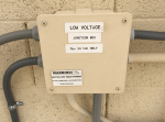
So my valve actuator conduit ran from the vicinity of the valves up to a J-box on the wall. There I made the connection using the connectors pictured above. Then I ran the individual 5 conductor wires for each of the the six IntelliValves through a major 1" low voltage conduit that runs from the low voltage J-box and into the left side punch-out into the low voltage raceway in the load center. This conduit not only contains the wiring for the six IntelliValves but also the control wiring for the IntelliChlor/IntellipH and the heater control wires. There in the low voltage raceway, I had to make the 6 individual connections using those electrical connectors once again in order to connect to the 3-pin (5 conductor) IntelliValve connector cable.
I used a 3/4" strain relief cable gland type connector where the conduit came out of the ground such as this. Another tip (I think you already know or practice this), when you pull the cable, pull an extra zip (pull) line, just in case something changes in the future.

Arlington LPCG757-5 3/4-Inch Strain Relief Electrical Cord Connector, 5-Pack - Conduit Fittings - Amazon.com
smile.amazon.com
I used this 22AWG wire, It worked great and that way I could keep the all of the color coding standardized. You'll end up with a whole bunch of extra blue wire.


Here are some related photos.


Good luck with the project.
As always, please feel free to reach out if I can help at all.
Hope you and the fam are doing great.
TTYL
r...


