T-CELL Voltage Sensor Short Chlorinator1

ek1

Active member
Oct 27, 2015
25
New York
I have a Hayward Omnilogic system connected to a Hayward Turbo Cell 15 (GLX-CELL-15-25). In August 2020 I made a horrible mistake of upgrading the Omnilogic firmware to 4.0.0. Immediately after the firmware upgrade the chlorinator started displaying an error "T-CELL Voltage Sensor Short Chlorinator1". As a side note, Omnilogic also lost an ability to control my pool heater, but that's a separate issue. I tried several troubleshooting steps, including:
1. Powering the system off/on
2. Re-seating the Turbo Cell connector cable
3. Removing the chlorinator from Omnilogic configuration and re-adding it
4. Rolling the Omnilogic firmware back to 3.x
Nothing worked. The error remained.
I contacted Hayware support and after several troubleshooting steps, they told my Turbo Cell failed and I need a new one. I decided to wait until next season to tackle the issue.

A week ago I opened the pool for the season and installed a brand new Turbo Cell 15. The SAME error message appeared. This means that there was potentially nothing wrong with the old Turbo Cell and Hayward gave me incorrect info. I tried the following troubleshooting steps:

1. Read Hayward's Omnilogic troubleshooting guide. My error message is NOT in their SWG troubleshooting chart and the only thing the flowchart recommends is to replace the main board (yeah, OK).
2. Checked ALL fuses in the system - all are OK
3. Checked the Turbocell connector - it is NOT burned or corroded
4. Tried removing the chlorinator from Omnilogic configuration and re-adding it
5. Read all the posts on the internet (including on this forum) that refer to this error message.
6. Checked the salt level - it's 3200ppm.

The Turbo Cell seems to be reading a correct salt level (average salt) because I saw the measurement go up from 3200 to 3300 after I added a bag of salt to the pool.

I also opened a case with Hayward, but I dont have high confidence in their ability to troubleshoot the issue since they already misdiagnosed it the first time around.
 
Here are the current chlorinator stats shown by Omnilogic:

Cell Temp:82.0°FCell Voltage:0.00 V
Instant Salt:0 ppmCell Current:0.00 A
Average Salt:3300 ppmCell Type:T-Cell-15
Relay Polarity:OFF
 
Here are the current chlorinator stats shown by Omnilogic:

Cell Temp:82.0°FCell Voltage:0.00 V
Instant Salt:0 ppmCell Current:0.00 A
Average Salt:3300 ppmCell Type:T-Cell-15
Relay Polarity:OFF
Did you ever resolve this? I am having same issue. Thanks!
 
Did you ever resolve this? I am having same issue. Thanks!
No, nothing has been resolved.

I have been working with Hayward support on this for OVER A MONTH NOW. They are giving me a runaround. First they told me to go to their web site and look at the list of "authorized" pool specialists that can service Omnilogic. They had about 8 companies in the list within a 25-mile radius, I contacted every single one of them. Most did not even bother responding. Out of those that responded, most said they either dont have a clue about what Omnilogic is or they dont service is. This means Hayward is giving out this "authorized" status to random pool companies without bothering to check if they can actually work on Hayward products. What a shame.

After the "contact authorized pool professional" fiasco, I contacted Hayward again. Their regional rep (I was not given their name) provided me with a contact of a company that allegedly services Omnilogic. I have called them and tried to make an appointment. They asked me for some info (Model and serial # of the Omnilogic, etc) and then stopped responding. I am now back to square one - emailing Hayward (there is NO phone support) and waiting for 1+ week for each response.

I now realize that Hayward is one of the worst companies I ever dealt with. They do not stand behind their products and what's even worse - they don't actually have anyone in the field that can work on their pool automation systems, at least in my area (NYC). So...one of the biggest pool equipment manufacturers in the world does not have ANYONE that can repair a system that has been in the market for over 5 years, in an area with a population of over 10 million people. Let that sink in. This is mind boggling.

Anyone considering Hayward products for their pool needs to read this and know that when (not if) things go wrong, they can count on Hayward leaving them high and dry.
 
Did you measure the voltage from the transformer yellow leads?

Are there any burnt marks on the back of the board near the K1 relay?

When the SWG engages, do you hear a click?

Is the unit still generating chlorine or are you having to manual dose?
 
Did you measure the voltage from the transformer yellow leads?

Are there any burnt marks on the back of the board near the K1 relay?

When the SWG engages, do you hear a click?

Is the unit still generating chlorine or are you having to manual dose?
* The transformer is producing 24VAC at the yellow leads, so it's working (at least that's what the troubleshooting guide says)

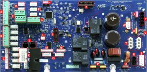
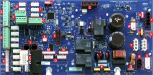
* I don't know where the K1 relay is (its not on the Hayward diagram). Can you please tell me where the relay is (Page 6 of the troubleshooting guide I posted has a full board picture of the Omnilogic). I did check the actual SWG connector (both sides, male and female) and there are NO burn marks. It looks pristine.

* The only time I hear a click is if I do the following:

1. Turn the chlorinator off in Omnilogic settings (which clears the "T-CELL Voltage Sensor Short Chlorinator1"error)
2. Power off the Omnilogic, wait for a minute, power it back on
3. Turn the chlorinator on in Omnilogic settings.

If I perform the steps above, I hear a click and a faint humming noise and after a few secons (3-5), the chlorinator error re-appears in the Omnilogic settings.

* The unit has not produced any chlorine since I started getting this error last year. I am not adding chlorine manually. Just using Clorox 6 in 1 Extra Blue once in a while to keep the algae in check and running the pump on a max speed 24/7.

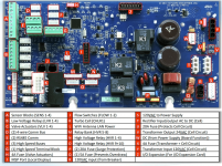
Another thing worth mentioning - in the Troubleshooting Guide Starting from Page 42 (Chlorinator troubleshooting), one of the steps is "Verify rectifier wiring, is it correct?" I dont know how to verify whether rectifier wiring is correct. The board diagram on Page 6 of the guide lists "T: Rectifier Input/output AC to DC (Cell)" and those two white connectors are occupied by cables going to the transformer. I re-seated both cables just in case and checked the connectors (all clean).

Thank you for replying BTW. I just don't know what else to do to get my system working again, so any advice helps.
 
Ok so it sounds like it is turning on but then there might be a short between the SWG power leads. That could be due to the other relays (K2 & K3). K1 connects the AC power to the rectifiers and K2 and K3 swap the plus and minus leads to change polarity. If one of the relays changes but the other doesn't, then there is a short although, I would have thought that the fuse would blow under that condition so I am not entire sure that is the cause. Another possibility is the sensor that measures voltage between the +- from the rectifiers. The problem is these boards are not all that easy to fix or troubleshoot. The only thing that is easy to fix is a bad solder joint on K1 which is the usual culprit of these types of problems. K1 has three leads that you can see if you turn over the board. If there is a problem there the solder joint might look burn and/or dull. You did check fuse U correct?

1627674722677.png
 
  • Like
Reactions: dmann33
Mas985 comments are very helpful. Unfortunately, if I had to guess, I would say the board is bad and agree with mas985 that the sensor that measures voltage from the rectifiers is suspect. Your board rev date is exactly the same as mine which was installed Aug 2020. It’s too bad the pool installer doesn’t have a spare board to swap out to confirm any of this. I agree with you on Hayward support - see my other posts. Good luck!
 

Enjoying this content?

Support TFP with a donation.

Give Support
Can anyone help me identify a varistor on a Hayward Omnilogic board? Here is a picture of the board with the part in question circled in red.

The varistor needs to be replaced because it basically crumbled when touched.


varistor.JPG
 
I have a friend that works in a company that repairs electronics for a living. He inspected the board with a microscope and found no physical damage with solder joints, etc. However, he did find a varistor that literally crumbled into pieces when touched. Here is a pic of where it was:
varistor.JPG

Since Hayward does not publish a proper board diagram, he tried replacing it with another varistor rated for 120V. I created a separate post asking if anyone knows the rating of this varistor, but I'm not holding my breath. According to him, the purpose of the varistor there is to prevent a voltage spike and/or a spark when the relay breaks the circuit (which makes sense). He also swapped top and bottom relays (K1 and K3) between each other (I figured we have nothing to lose at this point, especially since he has some very advanced electronics & diagnostics equipment at work). After the swap and varistor replacement, I _STILL_ have the same "T-Cell Voltage Sensor Short Chlorinator 1" message, but now I also have 3 more messages:

"T-Cell Current Sensor Short Chlorinator 1"
"CHLOR Relay K1 Stuck Open Chlorinator 1"
"CHLOR Relay K2 Stuck Open Chlorinator 1"

I ordered 3 replacement OMRON relays on Amazon, they should arrive on Monday and my friend will replace them.
 
Ok so it sounds like it is turning on but then there might be a short between the SWG power leads. That could be due to the other relays (K2 & K3). K1 connects the AC power to the rectifiers and K2 and K3 swap the plus and minus leads to change polarity. If one of the relays changes but the other doesn't, then there is a short although, I would have thought that the fuse would blow under that condition so I am not entire sure that is the cause. Another possibility is the sensor that measures voltage between the +- from the rectifiers. The problem is these boards are not all that easy to fix or troubleshoot. The only thing that is easy to fix is a bad solder joint on K1 which is the usual culprit of these types of problems. K1 has three leads that you can see if you turn over the board. If there is a problem there the solder joint might look burn and/or dull. You did check fuse U correct?

View attachment 359919
Yes, I checked all the fuses 3 times and reseated them. Do you know where this voltage sensor is?
 
This may be a bad suggestion; but, what if you took out the varistor and substituted a resistor just to see if the error message changes. If I understand correctly, a varistor will exhibit almost infinite resistance when below the threshold voltage. Anyway it’s used to suppress voltage spikes but for a one shot test, it may provide useful diagnostic information. It would be cool if your error message went away and now all you have to do is get another varistor.

Also, if it would help, I can try to take a picture of mine and see if there are any numbers. From what I understand, there are several parameters that would have to be matched. I wonder if Hayward could help identify?
 
  • Like
Reactions: C0d3Sp4c3
I have a friend that works in a company that repairs electronics for a living. He inspected the board with a microscope and found no physical damage with solder joints, etc. However, he did find a varistor that literally crumbled into pieces when touched. Here is a pic of where it was:
View attachment 361685

Since Hayward does not publish a proper board diagram, he tried replacing it with another varistor rated for 120V. I created a separate post asking if anyone knows the rating of this varistor, but I'm not holding my breath. According to him, the purpose of the varistor there is to prevent a voltage spike and/or a spark when the relay breaks the circuit (which makes sense). He also swapped top and bottom relays (K1 and K3) between each other (I figured we have nothing to lose at this point, especially since he has some very advanced electronics & diagnostics equipment at work). After the swap and varistor replacement, I _STILL_ have the same "T-Cell Voltage Sensor Short Chlorinator 1" message, but now I also have 3 more messages:

"T-Cell Current Sensor Short Chlorinator 1"
"CHLOR Relay K1 Stuck Open Chlorinator 1"
"CHLOR Relay K2 Stuck Open Chlorinator 1"

I ordered 3 replacement OMRON relays on Amazon, they should arrive on Monday and my friend will replace them.
Interesting! I have no experience with this pcb in particular but the Electronics in me is suggesting that the part circled in RED may not be a Varistor at all as your friend claimed. Would you know if the circled component part carries or installed across/inline with the AC Voltage? Can you post pictures of the pcb showing the solder side of the device in question? Looks like the marking on the board is RZ? (pls correct me if I am wrong) which often refers to a Thermistor aka inrush current suppressor. In order to confirm, you need to read the marking printed on the device itself or if unreadable, measure the resistance from a known good one.
 

Enjoying this content?

Support TFP with a donation.

Give Support
Thread Status
Hello , This thread has been inactive for over 60 days. New postings here are unlikely to be seen or responded to by other members. For better visibility, consider Starting A New Thread.