WATER PRESSURE SWITCH TEST / ADJUSTMENT PROCEDURE:
The pressure switch is preset at the factory for most typical, deck level installations.
When the heater is located above or below the level of the pool or spa, the pressure switch may require adjustment to compensate for the change in static head pressure.
The following procedure is recommended when the switch needs adjustment and/or is replaced:
For Installations with Heater Above Water Level:
1. Be sure the filter is clean before making the adjustment.
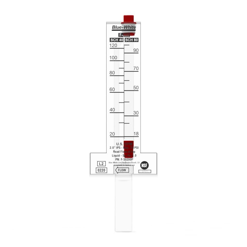
2. Turn “ON” the filter pump and ensure all air is out of the water lines, and ensure water flow rate is at least the rated minimum (see Table 14).
3. Turn “ON” the heater and adjust the thermostat to create a call for heat.
4. If the heater does not light, adjust the pressure switch by turning the adjustment knob on the pressure switch counter-clockwise, until the heater lights.
Turning the adjustment knob counterclockwise decreases the pressure needed to close the switch.
5. Check the function of the pressure switch by turning the filter pump on and off several times. The pool heater should turn off immediately when the pump is turned off. Never allow the heater to operate with less than the minimum rated water flow rate.
For Installations with Heater Below Water Level:
1. Be sure the filter is clean before making the adjustment.
2. Turn “ON” the filter pump and ensure all air is out of the water lines, and ensure water flow rate is at least the rated minimum (see Table 14).
3. Turn “ON” the heater and adjust the thermostat to create a call for heat.
4. Turn the adjustment knob on the pressure switch clockwise, until the heater turns off, then turn the knob ¼ turn counter-clockwise, so that the heater turns back on. Turning the adjustment knob clockwise increases the pressure needed to close the switch.
5. Check the function of the pressure switch by turning the filter pump on and off several times. The pool heater should turn off immediately when the pump is turned off. Never allow the heater to operate with less than the minimum rated water flow rate.
Two-speed pump:
In a few cases the pressure from a two-speed pump is below the 1- pound minimum required to operate the water pressure switch on the heater.
This is apparent when the pressure switch cannot be further adjusted. In these cases the pump must be run at high speed to operate the heater. If the pump and piping arrangement are such that the re-quired 1-pound minimum pressure cannot be obtained, do not attempt to operate the heater. Correct the installation.