AQUA~HOLICS
In The Industry

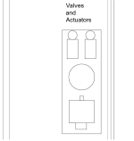
Thanks again for your input. Other than that question about skimmer excavator get a great job all measurements and elevations were dead on. They were done in 4 hrs.It actually looks to be of normal size.View attachment 559939
Leave more space between garage wall and equipment is all I can figure. I will home when they start working. I can ask for more questions before they set the equipment..Did he give a reason for this?


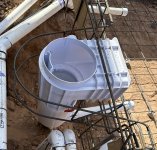
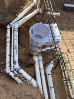
Thanks, I measured them, the filtration pump is 11 1/2” and the SPA pump is 13”. Both are close but should have been a bit longer. Surprises me that they do not know this considering they do it for a living.The Pentair pump installation manual says “valves, elbows, or tees in the suction line shall be no less than 5 times the suction pipe diameter from the pump inlet”. So if 2.5” diameter, should have 12.5” straight pipe in front of inlet.View attachment 560341
I checked clearance there should be enough space to slide pump back from coupler to replace pump. Hopefully that will be years away.A few things to consider,
Pipe directly behind the main pump may make it difficult to replace the motor in the future.
There will be a SPA blower on the pipe.If the pipe with the gauge installed is an air line for the spa, have two 90 fittings installed after the gauge is removed and left open on the end for maximum efficiency.
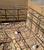
I know most of the ID’s. Filtration Pump suction closest is SPA filtration, the next 3 are skimmer, main drain and vacuum port. Which of those 3 would you not place a valve on? Thanks for the tips and feedback!ID decals placed on the plumbing pipes for future reference of their purpose.View attachment 560361

There is a step in corner of SPA but no rebar. Is the supposed to be steel in corner? ThanksFrom the picture provided unable to see if the spillway from the spa to the pool is properly bent for the correct size.
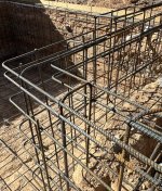
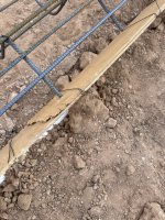
Can you provide a picture of the skimmer cut out with the cage around it?
Thanks for the feedback so far. I’m not sure which pipes you are referring to. I added the full photo to help me understand.The picture of the skimmer shows 2 plumbing pipes in the background very near the rebar, plumbing pipes that travel in and out of the Shotcrete shell (like in the picture) may be cause for concern from a movement standpoint. The shotcrete has the least likely chance to move but the plumbing surrounded by dirt may and keeping them separate from each other as much as possible is best.