This post is a writeup of a recent repair that I made to a Pentair MicroBrite Color LED light. If you own these lights, you know that they give out excellent light but are very expensive ($400+) for what they are. So when they go bad and are out of warranty (or you didn’t qualify for warranty because you didn’t have a “professional” install them), forking out another $400 is not very appealing.
I had a couple of my lights start to glitch after 2.5 years of use. This manifested as loss of color or periodic flashing / loss of light. So I removed them and looked into the possibility of repair. Previously I had Savi Melody lights which could not be repaired because of the way they were constructed and I was expecting the same with the MicroBrites. Obviously waterproofing the lights is key and that is usually what prevents a repair.
Before getting into what I did, let me just say that I do a lot of electronics tinkering and I have equipment that helps with this type of job. If you only have one light to repair and are not adept at testing and soldering electronics, you probably will be better off buying a new light.
Disassembly
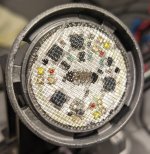
Disassembly of the light proved to be remarkably simple. Using a pair of snub-nosed pliers, the lens can be gently squeezed out of the surrounding housing, being careful not to break the gray plastic. The circuit board holding the LEDs is covered with a pliable clear gel between the lens and the board. That, along with an O-ring, provides the sealing and waterproofing. It was easy to peel off the board, but care needs to be taken not to damage the LEDs.

Once the lens is removed, it is worthwhile powering up the light to get an idea of what is wrong. This requires a 12VAC power supply. I recommend a landscape lighting transformer for this – check the output with a multimeter to make sure it is putting out 12VAC or less. When you power on the light, be aware that the LEDs are extremely bright, so placing it behind some sort of diffuser will be necessary. Check the light to determine which colors are not working – this will require switching the light on and off to cycle through the sequences listed in the user manual.
How it works
The light consists of two sets of electronics. The power and control circuitry is housed in the body of the light and is inaccessible. The LEDs and their control circuitry is on the upper circuit board exposed when the lens is removed. That circuit board is quite simple and it may be immediately obvious where problems lie.
Power for the different LED colors is sourced through the central connector. The light houses four colors of LEDs – red, green, blue and white – and there is one power pin per color on the connector. The LEDs themselves are pretty robust. They are Lumileds LUXEON C Color Line LEDs and are extremely small (2.0mm square). Each LED is less than $2, and they are easy to source. I believe the blue LED is actually Royal Blue, not the standard blue. Look for part numbers like L1C1-RYL1000000000. I think it is unlikely that the LEDs will fail, although I did damage one of mine during disassembly and had to replace it.
The LEDs are arranged in 3 groups of 4 LEDs, with R, G, B and W in each group. This is only for distributing the light evenly. The electronics that drive the LEDs is replicated 4 times on the board, once for each color.
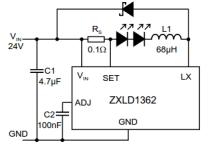
Each driver circuit is oriented around a Zetex ZXLD1362 LED driver chip. These are the 5-pin chips you see on the board. In my photos you will see one that has basically disintegrated – obviously a problem. These chips are less than $3 each. If you look at the datasheet for the chip, you will find the rest of the circuitry on the board:

The resistor value is a little different and there’s only one capacitor per circuit. Each circuit basically drives one LED color, with the 3 LEDs connected in series.
The larger black square components on the board are the inductors (L1). The small 2-legged black components are the Schottky diode at the top of the schematic. This is a Nexperia PMEG2020EJF which costs around 30 cents. One of these had disintegrated too on my light.
Repair
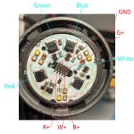
The board just pulls off of the light housing and you can then clean it up and probe it with a meter to test the components. I have yet to reverse engineer the schematic, but was able to figure most of it out (see annotated diagram). If you very carefully apply 12V DC to the various pins, the LEDs will light up.

The repair is basically repairing the broken components. In my case, the inductors, resistors and capacitors were fine, I just had driver chips and Schottky diodes to replace. The challenge is dealing with the tiny sizes. You cannot use a soldering iron, since the circuit board is backed by aluminum which is a heat sink, plus the components are just too small. I used a very small board heating plate to remove and replace the components.
Running it at 235C, I placed a section of the board on the plate and held it there with the tips of needle nose pliers. You have to be careful not to get the central connector in contact with the plate, because it will melt! After about 45s, the components will desolder and you can remove them very carefully with pointed tweezers. Then use another pair of pliers to gently remove the board from the plate (it's extremely hot!) and let it cool. You will need to clean up the pads with isopropyl alcohol, apply some solder paste (I used a pointed cocktail stick for this), then place the new components in place. Heat the board again to fuse them into place.
You can test the board with 12V DC, then reinsert it into the housing and do a more thorough test using the 12VAC supply.
The clear gel that was removed during disassembly appears to be some sort of optically clear encapsulant, similar to what you see on flexible LED strips. It is very difficult to find in tiny quantities so I decided to take a chance and use a household caulk. This was DAP Seal 'n Peel, which is a clear caulk that dries while remaining flexible and removable. It’s quite goopy, so I put about 4ml into a syringe and heated that in hot water. I applied that to the back of the lens and then carefully squeezed the lens back into place, which spread out the caulk quite nicely. To date, this has been working fine in my pool!
Bearing in mind I already had the equipment to perform the repair, my actual cost to repair one light was less than $15, the most expensive piece being the $8 tube of caulk. If you have the time, I think it’s worthwhile trying to fix these lights vs. buying new ones.
I hope this is helpful to some of you!
I had a couple of my lights start to glitch after 2.5 years of use. This manifested as loss of color or periodic flashing / loss of light. So I removed them and looked into the possibility of repair. Previously I had Savi Melody lights which could not be repaired because of the way they were constructed and I was expecting the same with the MicroBrites. Obviously waterproofing the lights is key and that is usually what prevents a repair.
Before getting into what I did, let me just say that I do a lot of electronics tinkering and I have equipment that helps with this type of job. If you only have one light to repair and are not adept at testing and soldering electronics, you probably will be better off buying a new light.
Disassembly
Disassembly of the light proved to be remarkably simple. Using a pair of snub-nosed pliers, the lens can be gently squeezed out of the surrounding housing, being careful not to break the gray plastic. The circuit board holding the LEDs is covered with a pliable clear gel between the lens and the board. That, along with an O-ring, provides the sealing and waterproofing. It was easy to peel off the board, but care needs to be taken not to damage the LEDs.

Once the lens is removed, it is worthwhile powering up the light to get an idea of what is wrong. This requires a 12VAC power supply. I recommend a landscape lighting transformer for this – check the output with a multimeter to make sure it is putting out 12VAC or less. When you power on the light, be aware that the LEDs are extremely bright, so placing it behind some sort of diffuser will be necessary. Check the light to determine which colors are not working – this will require switching the light on and off to cycle through the sequences listed in the user manual.
How it works
The light consists of two sets of electronics. The power and control circuitry is housed in the body of the light and is inaccessible. The LEDs and their control circuitry is on the upper circuit board exposed when the lens is removed. That circuit board is quite simple and it may be immediately obvious where problems lie.
Power for the different LED colors is sourced through the central connector. The light houses four colors of LEDs – red, green, blue and white – and there is one power pin per color on the connector. The LEDs themselves are pretty robust. They are Lumileds LUXEON C Color Line LEDs and are extremely small (2.0mm square). Each LED is less than $2, and they are easy to source. I believe the blue LED is actually Royal Blue, not the standard blue. Look for part numbers like L1C1-RYL1000000000. I think it is unlikely that the LEDs will fail, although I did damage one of mine during disassembly and had to replace it.
The LEDs are arranged in 3 groups of 4 LEDs, with R, G, B and W in each group. This is only for distributing the light evenly. The electronics that drive the LEDs is replicated 4 times on the board, once for each color.
Each driver circuit is oriented around a Zetex ZXLD1362 LED driver chip. These are the 5-pin chips you see on the board. In my photos you will see one that has basically disintegrated – obviously a problem. These chips are less than $3 each. If you look at the datasheet for the chip, you will find the rest of the circuitry on the board:

The resistor value is a little different and there’s only one capacitor per circuit. Each circuit basically drives one LED color, with the 3 LEDs connected in series.
The larger black square components on the board are the inductors (L1). The small 2-legged black components are the Schottky diode at the top of the schematic. This is a Nexperia PMEG2020EJF which costs around 30 cents. One of these had disintegrated too on my light.
Repair
The board just pulls off of the light housing and you can then clean it up and probe it with a meter to test the components. I have yet to reverse engineer the schematic, but was able to figure most of it out (see annotated diagram). If you very carefully apply 12V DC to the various pins, the LEDs will light up.

The repair is basically repairing the broken components. In my case, the inductors, resistors and capacitors were fine, I just had driver chips and Schottky diodes to replace. The challenge is dealing with the tiny sizes. You cannot use a soldering iron, since the circuit board is backed by aluminum which is a heat sink, plus the components are just too small. I used a very small board heating plate to remove and replace the components.
Running it at 235C, I placed a section of the board on the plate and held it there with the tips of needle nose pliers. You have to be careful not to get the central connector in contact with the plate, because it will melt! After about 45s, the components will desolder and you can remove them very carefully with pointed tweezers. Then use another pair of pliers to gently remove the board from the plate (it's extremely hot!) and let it cool. You will need to clean up the pads with isopropyl alcohol, apply some solder paste (I used a pointed cocktail stick for this), then place the new components in place. Heat the board again to fuse them into place.
You can test the board with 12V DC, then reinsert it into the housing and do a more thorough test using the 12VAC supply.
The clear gel that was removed during disassembly appears to be some sort of optically clear encapsulant, similar to what you see on flexible LED strips. It is very difficult to find in tiny quantities so I decided to take a chance and use a household caulk. This was DAP Seal 'n Peel, which is a clear caulk that dries while remaining flexible and removable. It’s quite goopy, so I put about 4ml into a syringe and heated that in hot water. I applied that to the back of the lens and then carefully squeezed the lens back into place, which spread out the caulk quite nicely. To date, this has been working fine in my pool!
Bearing in mind I already had the equipment to perform the repair, my actual cost to repair one light was less than $15, the most expensive piece being the $8 tube of caulk. If you have the time, I think it’s worthwhile trying to fix these lights vs. buying new ones.
I hope this is helpful to some of you!
Last edited:

