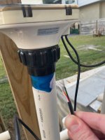
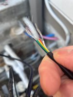
Hi, has anyone wired a pentair intellilevel automatic pool filler up before? I believe the prior pool builder cut the cord coming off the intellilevel to the control panel (easytouch 8 in my case). From the intellilevel manual it looks like it is suppose to be a three wire cord with a connector that goes into an actuator valve spot on the control panel. The issue is the cord coming from the intellilevel to the control panel is 5 wire (black, red, white, yellow, green). See attached pictures. Anyone have any idea on this? I called pentair and they said it's suppose to be 3 wire (not 5). Should I just hook the black, red, white to a 3 pin connector (see link below) and connect to a valve spot on the easytouch 8? Then wire nut the yellow/green? Thanks for your help

Pentair Intellilevel wiring question
- Thread starter ejhasan
- Start date
-
- Tags
- intellilevel
You are using an out of date browser. It may not display this or other websites correctly.
You should upgrade or use an alternative browser.
You should upgrade or use an alternative browser.


IntelliLevel™ Automatic Water Leveling System
The best water level for new construction with pool automation. With the IntelliLevel Water Leveling Monitor’s multi-sensing technology, your pool’s water level stays at just right amount, no more overflowing or wasting water.
Yellow and green are for communications.
The communications might not be enabled yet.
You have to ask Pentair about that.
The black, red and white are for power.
The black goes to the Common pin on any valve actuator and the red and white go to the switched legs of the valve actuator socket so that the IntelliLevel can get 24 VAC power regardless of if the valve is open or closed.
Connecting Power to the IntelliLevel Automatic Water Leveling System (EasyTouch and IntelliTouch Control Systems).
The IntelliLevel system controller 3-pin power cable connects directly to any unused Valve Actuator 24V power socket located on the EasyTouch or IntelliTouch Control Systems circuit board.
The IntelliLevel controller is designed to operate regardless of whether the valve actuator is in the ON or OFF position.
The IntelliLevel controller wire is marked PWR.
The communications might not be enabled yet.
You have to ask Pentair about that.
The black, red and white are for power.
The black goes to the Common pin on any valve actuator and the red and white go to the switched legs of the valve actuator socket so that the IntelliLevel can get 24 VAC power regardless of if the valve is open or closed.
The Yellow and Green are not used unless the communications function has been activated.
If it has been activated, then the yellow and green go to the communication terminal.
The black, red and white get connected to a valve actuator as shown below.
If you are connecting to a 24 VAC transformer directly, the black and white are connected and the red is capped off.
Black should be common and the red and white wires should be the switched legs.
Black - Common
Red - Switch Leg
White - Switch Leg
Note that the voltage is AC, not DC.
You should measure 24 volts AC from black to red or black to white when the valve is off.
When the valve is on, the voltage switches from red to white or white to red.
So, if you had 24 volts AC from red to black with the valve off, the voltage should be 24 volts AC from white to black when the valve is on.
Is there a cut cord in the EasyTouch?I believe the prior pool builder cut the cord coming off the IntelliLevel to the control panel (EasyTouch 8 in my case).
Hey JamesW. Thanks so much for you help. That is all really helpful! Really do appreciate it. There is no cut cord in the EasyTouch (unfortunately). I think I just need to buy a 3 pin connector. I think this is the right one? Amazon.comIs there a cut cord in the EasyTouch?
Stupid question: it looks like when they connect the wires to the 3 pin connector they don't strip them first? I guess it just cuts the wire when put in. I always thought having wire insulation next to an active wire is a fire risk. Maybe because it is low voltage it is okay. Thanks James
The insulation displacement connection (also known as IDC) is a particularly time-saving connection technology.
With this connection method, the cutting metal cuts through the insulation and establishes a reliable connection to the conductor.
Since insulation displacement technology eliminates the need to strip the insulation and apply splice protection to the conductors, you save considerable time compared to conventional connection technologies.
Conductor connection takes only a few seconds.
Reliable contacting with the IDC connection is achieved by inserting the conductor into the specially shaped cutting metal.
Thread Status
Hello , This thread has been inactive for over 60 days. New postings here are unlikely to be seen or responded to by other members. For better visibility, consider Starting A New Thread.