Heater settings

cmiller73

Well-known member
May 1, 2012
262
Houma, LA
Pool Size
12500
Surface
Plaster
Chlorine
Salt Water Generator
SWG Type
Pentair Intellichlor IC-40
My heater, Pentair Mastertemp 400, will not come on without my main pool circuit on. That circuit has the pump and chlorinator on it.
I have set a feature on my ET so that when I want to heat pool, my pump will also come on at a certain gpm.

Is there a setting in the ET configuration that requires the pool main pool circuit to be on when heater is needed?

What I am trying to accomplish, now that I have the pump kicking on when heater is turned on via pump feature, is to run heater without chlorinating if I so choose. I have a schedule set up and don't want to mess with it. So when/if I decide to turn heater on, I can do that no matter what schedule is running.
 
Last edited:
Thanks for the reply guys.
After opening the panel, the only thing that triggers the heater on/off is the com cable that is attached to the main pc board. There are no wires from the breaker to the relay circuit that the pump/cell is on.

That seems to be the root of your problem. If you can separate the chlorinator from the Pool circuit and put it on its own circuit, you'll be able to run the pool alone, pool + chlorinator, pool + heater, or pool + heater + chlorinator.
Putting pump on 1 circuit and the chlorinator on another? Is that normal?
I only have 4 circuits/relays. pool/chlorinator on 1, intellibrights on 1. That leaves 2 open. Moving chlorinator to it's own would take up another. Leaving me with only 1, which will be landscape lights later on. So that would fill all relays.
But then I could add more relays if needed at a later date? Right?

If I do this, I then would have to figure out how to program it. I guess it would be somewhat like I did the "heat pool" feature in the intelliflo settings, so the pump runs at the set gpm.
 
Last edited:
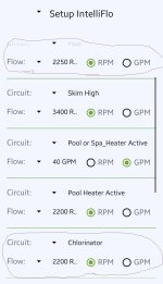
Kinda messed around with the setup on my phone. As you can see the new circuit at the bottom "Chlorinator" (which would be on Aux 3 alone when I rewire) is made and will trigger pump to come on and run at 2200rpm. All I would then do is set the schedule to run in the place of my current(at top of list) "Pool/chlorinator" schedule. Correct?

ScreenshotSLConfig.jpg
 
That seems to be the root of your problem. If you can separate the chlorinator from the Pool circuit and put it on its own circuit, you'll be able to run the pool alone, pool + chlorinator, pool + heater, or pool + heater + chlorinator.
Doing a bit of digging and reading, I did run across this.
"The IC40's transformer must be wired to the load side of the pump filter relay."

So obviously Pentair doesn't recommend putting the IC on it's own relay.
 
Doing a bit of digging and reading, I did run across this.
"The IC40's transformer must be wired to the load side of the pump filter relay."

So obviously Pentair doesn't recommend putting the IC on it's own relay.

Run the LINE power to your AUX3 chlorinator relay from the LOAD side of the filter pump relay.

That keeps the chlorinator from being powered when the pump is not powered, which is what Pentair wants and gives you separate control over the chlorinator.
 
Run the LINE power to your AUX3 chlorinator relay from the LOAD side of the filter pump relay.

That keeps the chlorinator from being powered when the pump is not powered, which is what Pentair wants and gives you separate control over the chlorinator.
Gonna have to see how it is wired again and then try to understand what you mean. Would no "load" go to aux3 relay? Just "line"? That requires a jumper right?
 
So I tie a jumper directly into the "load line" for the pump relay. Not #2 side as it is now.
That was the only way chlorinator gets power is when the pump is on?
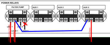
Is this right?
1710344662467.png


Edit.
Do "Load sides" work independently? I'm guessing they do since there is a dedicated "line" for each. I've not messed with any wiring since install. I'm guessing contractor does it this way because it is easier to figure out instead of jumping from 1 relay to another.
 
Last edited:

Enjoying this content?

Support TFP with a donation.

Give Support
Your IntelliPro pump is 240V.

Is your Intellichlor power supply wired for 120V or 240V?

Do you have a GFCI CB for your pump as code requires?

1710344662467-png.558053


The diagram above that you supplied implies a 120V feed for the Intellichlor. I do not know what the red X means on the filter pump LOAD2 line. That will not work with a GFCI CB.

You are stumbling on this and lack some fundamental electrical knowledge that concerns me.
Edit.
Do "Load sides" work independently? I'm guessing they do since there is a dedicated "line" for each. I've not messed with any wiring since install.

I do not understand what you are asking.

Each relay works independently.

When a relay closes the electricity on LINE1 connects to LOAD1 and LINE2 connects to LOAD2.

A 120V circuit has one hot line and a 240V circuit has two hot lines. So 240V relay control uses LINE1/LOAD1 & LINE2/LOAD2.

I'm guessing contractor does it this way because it is easier to figure out instead of jumping from 1 relay to another.

Contractor does what "this way"? I cannot follow what you are talking about.
 
Your IntelliPro pump is 240V.
Yes

Is your Intellichlor power supply wired for 120V or 240V?
Pretty sure it is. I had to wire it after installer forgot to connect correct wires on the transformer. Long story.

Do you have a GFCI CB for your pump as code requires?
I do not think so. My transformer is in my panel. I have one only for light CB.

The diagram above that you supplied implies a 120V feed for the Intellichlor. I do not know what the red X means on the filter pump LOAD2 line. That will not work with a GFCI CB.
If I understand what you explained to me, that is the way I should wire it in order to control IC separately from main pool relay. Right now my IC is on line/load 2 on same relay as pump.

You are stumbling on this and lack some fundamental electrical knowledge that concerns me.
It has more to do with the relays and how they would act after wiring a certain way.

I do not understand what you are asking.
Each relay works independently.
When a relay closes the electricity on LINE1 connects to LOAD1 and LINE2 connects to LOAD2. That is what I was asking.
A 120V circuit has one hot line and a 240V circuit has two hot lines. So 240V relay control uses LINE1/LOAD1 & LINE2/LOAD2. Makes sense.

Contractor does what "this way"? I cannot follow what you are talking about. Putting both pump and IC on same relay. Easier that way than jumping to another relay and then having to program the ET to do certain things. I feel my contractor is not much when it comes to "custom" programming of ET.

I'll take a good picture of the inside when I get home today.
 
You should install a GFCI CB or your pump if you do not have on.


Your Intellichlor should be wired for 240V to be compatible with your 240V pump circuit and work with the GFCI CB.

I got involved with this because of your wiring question. I do not understand why you are going through this change when you can just let your IntelliChlor run the entire time your pump runs as most people do.
Will look at that GFCI info and change out. Just have to double check to make sure I don't have one. I'm pretty sure I do not. Only one I recall having one is light transformer CB.

Well, it started as a heater issue. Heater will not come on UNLESS pool circuit is on. I have my IC scheduled to run at a certain time. In the event I want to run heater, I really didn't want the IC kicking on at other times. Why? I guess just cause. With such a customizable system, which is what I wanted and paid for, it seems it really isn't that customizable as I thought.
 
Well, it started as a heater issue. Heater will not come on UNLESS pool circuit is on.

Which is correct and a safety issue if the heater was to try and run without the pump running.

I have my IC scheduled to run at a certain time.

Why?

Most people run the IC on the same schedule as the pump.

You want to generate chlorine anytime your pump is running ans water is circulating.

In the event I want to run heater, I really didn't want the IC kicking on at other times. Why? I guess just cause. With such a customizable system, which is what I wanted and paid for, it seems it really isn't that customizable as I thought.
As you are learning you can customize the wiring to run your system in non-standard ways if you choose to.
 
Which is correct and a safety issue if the heater was to try and run without the pump running.
That I understand from a safety standpoint.
However, if nothing is running and I decide to turn on heater, why can't it tell the system, "Hey look heater is on, let's turn the pump on" Whether I turn it on manually via feature or have it on a set schedule.
I did set a feature to run pump at lower rpm/gpm when heater is activated versus than running at whatever rpm set in other pump feature setting. seems that would tell the ET to turn on pump circuit(IC connected or not).

Why?
Most people run the IC on the same schedule as the pump.
You want to generate chlorine anytime your pump is running ans water is circulating.
Noted for sure.
At this time with no pool activity, I've been only running late evening until early morning. Trying to catch it back up since I've had a few issues with too much rain and water leakage around skimmers.

As you are learning you can customize the wiring to run your system in non-standard ways if you choose to.
Yes. Is is right or is it wrong though? Still learning.
 
I may be missing something in the SLconfig, but everything I have tried, will not allow heater to trigger pump circuit. Matter of fact, if pump circuit isn't on, heater is completely off.
Am I missing something?
 
Heater is bound to master pool, master spa features. These two features dictate the temp readings and demand. Most people will run their pool long periods of time with their ic running at a lower percentage to meet their demand. So your request is not a typical one. If you don’t have a spa, use that as your heat source when you don’t want the swg running. The swg will drop to 5% of whatever you have it set for the pool.
 
I may be missing something in the SLconfig, but everything I have tried, will not allow heater to trigger pump circuit. Matter of fact, if pump circuit isn't on, heater is completely off.
Am I missing something?

Nope, that the way it works.

Pentair designers made many simplifying assumptions about how the pool will operate. One of them is the Pool Circuit is used to indicate if the pool is on or off. Everything keys off of that.

You can start trying to twist the system to meet your ideas for the way you want it to work or keep it simple and understand what the designers intentions were.
 

Enjoying this content?

Support TFP with a donation.

Give Support