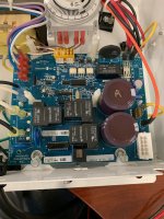
New to the forum but have been researching the issues with the PCB of the Aqua Trol for a month or so now without any luck. I have done all of the troubleshooting as detailed in the manual but seem to be stumped when it comes to pin 2 and 4 of the display board. I get readings way off from the norm. 22vdc on pin 4. Pin 2 I get nothing. Thermistor looks to be fine. Did a resistance test on it and numbers seems to be good. TP13 I get 5v. R17 I get 24v and 19v on right side. TP14 I get around 3 vdc which seems a little off as this should be 5vdc from what I have researched. Any help or suggestions would be greatly appreciated!

Hayward Aquatrol No Power No Display Help
- Thread starter halep1089
- Start date
You are using an out of date browser. It may not display this or other websites correctly.
You should upgrade or use an alternative browser.
You should upgrade or use an alternative browser.
C0d3Sp4c3
Well-known member
- Dec 10, 2018
- 258
- Pool Size
- 20000
- Surface
- Plaster
- Chlorine
- Salt Water Generator
- SWG Type
- Hayward Aqua Rite (T-15)
You have the newest sw r1.47
It is a catastrophe for pin 4 on the dsp bd to have 22vdc. I think this is a user error! Pin 2 is not Earth Ground but a Negative post as opposed to the positive terminal.
This video might help, just ignore the PSU >
It is a catastrophe for pin 4 on the dsp bd to have 22vdc. I think this is a user error! Pin 2 is not Earth Ground but a Negative post as opposed to the positive terminal.
This video might help, just ignore the PSU >
Thanks for your input! No matter what I try I continue to get around 22-24 vdc on my multimeter for pin 4. I have referenced that video before in diagnosing what the issue is. Could U13 still be the problem even if I am not getting 0 on TP14? I am getting around 3.7 vdc everytime.
Set the multimeter to DC volts and put one lead on pin 2 and one lead on pin 4 and measure the voltage.
Test a battery to make sure that your meter is reading the voltage correctly.


Test a battery to make sure that your meter is reading the voltage correctly.

C0d3Sp4c3
Well-known member
- Dec 10, 2018
- 258
- Pool Size
- 20000
- Surface
- Plaster
- Chlorine
- Salt Water Generator
- SWG Type
- Hayward Aqua Rite (T-15)
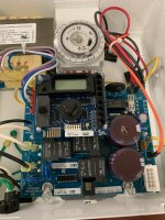
Can you please take pictures of the voltmeter readings and post them here? How can there be 22-24vdc if the supply line voltage is limited to 5 vdc at TP-13 output from the fixed 5-volt regulator (78M05)?Thanks for your input! No matter what I try I continue to get around 22-24 vdc on my multimeter for pin 4. I have referenced that video before in diagnosing what the issue is. Could U13 still be the problem even if I am not getting 0 on TP14? I am getting around 3.7 vdc everytime.

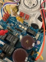
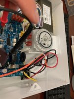
Sure. I also took a picture from one lead on post 2 and one on 4. I have replaced the fuse and the pins look perfectly straight. Battery test came back at 1.5v. I don't know much about these just interested in finding the problem as this is just under two years old and Hayward has rejected the warranty request.
Attachments
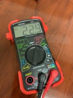
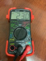
The display says MV, which is millivolts.
If you set the meter to DC volts and test a battery, does it show 1.5 volts without the mV?
If you set the meter to DC volts and test a battery, does it show 1.5 volts without the mV?
Last edited:
Can you go through the diagnostic tests in the troubleshooting guides and posts all results?
You are correct 1.5v not sure why it switches to mv when I test pin 4. Will post results.
C0d3Sp4c3
Well-known member
- Dec 10, 2018
- 258
- Pool Size
- 20000
- Surface
- Plaster
- Chlorine
- Salt Water Generator
- SWG Type
- Hayward Aqua Rite (T-15)
That's because your VOM is auto-ranging. Be cautious in observing the unit of measurement.You are correct 1.5v not sure why it switches to mv when I test pin 4. Will post results.
From your 1st post, TP-13 is 5 Vdc which is good. However, if TP-14 and header pin# 4 is 0 volt then most likely the U13 chip failed. When replacing the U13 chip, make sure the pins are soldered properly in place. A loose connection is highly likely to result in losing EEPROM data or getting stuck in Alarm-0 and bricking the pcb. You are warned!
2024 Annual Donation Campaign
Hi all, Thanks to the fervent support of the TFP community, we have met our $10,000 goal! We appreciate all the users in this thread hyping the campaign and sharing warm and fuzzy TFP anecdotes. Completion of this campaign reminds us that TFP is a resource that people can trust with their pool...
 www.troublefreepool.com

Become a TFP Supporter
Help Support TFP Trouble Free Pool is run by a dedicated group of volunteers that … Read more…
www.troublefreepool.com
Sorry for the delay!
So starting from step C: 123 vac
D: 24 vac
E: 2.6 ohms between white and blue 2.3 ohms grey and violet
F: Fuse good
G: 33 vdc
H: Still getting the 22-23 mv on pin 4
So starting from step C: 123 vac
D: 24 vac
E: 2.6 ohms between white and blue 2.3 ohms grey and violet
F: Fuse good
G: 33 vdc
H: Still getting the 22-23 mv on pin 4
C0d3Sp4c3
Well-known member
- Dec 10, 2018
- 258
- Pool Size
- 20000
- Surface
- Plaster
- Chlorine
- Salt Water Generator
- SWG Type
- Hayward Aqua Rite (T-15)
Thread Status
Hello , This thread has been inactive for over 60 days. New postings here are unlikely to be seen or responded to by other members. For better visibility, consider Starting A New Thread.