I have an old (2004-ish) Hayward Aquarite T-Cell 15. Over the years I have replaced the boards, cells, displays, etc. My current challenge is a blown fuse.....not the 20amp fuse on the board, but the 2.5amp fuse on the mounted on the bottom of the control box (see photo with cap removed). I can replace the fuse, return power and leave the main switch in "OFF", it all looks normal: Power light on, Display showing salt reading. The moment I switch to "Generate" and hear the click, the lights and display all begin to flicker, then go out and the fuse is blown. I have done this experiment multiple times and it is repeatable. See attached video.
In all the threads I have read, i don't read anything about this 2.5amp fuse; is it necessary?
Any ideas on why this fuse burns out when in "Generating"?
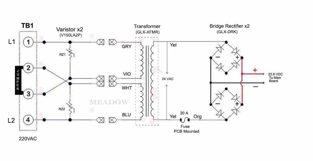
I have confirmed 240VAC across TB1, 2.5ohms resistance across Blue/White and Violet/Grey wires, and the 20amp fuse on the board is fine.
In all the threads I have read, i don't read anything about this 2.5amp fuse; is it necessary?
Any ideas on why this fuse burns out when in "Generating"?
I have confirmed 240VAC across TB1, 2.5ohms resistance across Blue/White and Violet/Grey wires, and the 20amp fuse on the board is fine.