AquaTrol RJ Lights Go Out Just After Turning On Generator

ChasPro

Active member
Jun 13, 2021
42
Buffalo, NY
Pool Size
13500
Surface
Vinyl
Chlorine
Salt Water Generator
SWG Type
Hayward Turbo Cell (T-CELL-5)
Symptoms: My swg “generating” light comes on then both "power" and "generating" go off.

I have power to the system with "power" light on. As the generating switch is turned from Off to Auto, the "generating" light comes on then voltage drops and both lights go off. The only way to get the "power" light back on is to unplug, wait, then plug in again with generator Off. Turn on ... stable "power" light and pump running ... turn on generator again ... and it fails the same way.

I have read the following guides:


When I test the thermistor, test point 1..5, and the J-plug pin voltages at my workbench (powered but maybe not generating?), they seem to be fine based on the basic tests in the guides. (I can discuss exactly what I'm doing if that helps). I'm not sure if the symptoms will only present themselves when in their operational setup (with everything attached/running) or if there is a way to troubleshoot further at the bench.

Advice on basic approach to testing and next steps? Thanks.
 
Last edited:
What are the first seven characters of the cell serial number?
 
Cell S/N: 3E20154... purchased just as the pandemic broke out, as my previous cell was already 8 yrs old.

Using an analog meter, so approximations. Base voltage on main board matches display at 29.5v. Other test points are near 5v as expected. That's at a bench, simply powered up. Nothing on. No cell connected. No pump motor connected.

Hold on one second here!! Just now, I powered up the unit at the bench to double check the V, and now it's measuring 20v at the red terminal (near thermistor) and 5.6v on display and output of thermistor.

Plugged in, pump switch set to On (possibly no lights except for No Flow blinking?). Generator set to Super. After a minute or two, No Flow stops blinking. Above V measurements still valid. 20v and 5.6v. While typing this, the unit clicked on, with power, generating, super lights on. 29.2v displayed... then some seconds later generating light Off, No Flow and Inspect Cell solid. Meter matches display, 29v on both sides of thermistor, RED power. Using R15 as gnd point for all measurements on test points. TB1 WHT to BLK for input V measurements. Input V is near 110v, as expected.
 

Attachments

  • PXL_20230813_122742815.jpg
    PXL_20230813_122742815.jpg
    280.4 KB · Views: 7
  • PXL_20230708_210948792.jpg
    PXL_20230708_210948792.jpg
    242 KB · Views: 8
  • PXL_20230708_210927064.jpg
    PXL_20230708_210927064.jpg
    415.4 KB · Views: 7
  • PXL_20230708_210428527.jpg
    PXL_20230708_210428527.jpg
    365.7 KB · Views: 8
  • PXL_20230708_210411539.jpg
    PXL_20230708_210411539.jpg
    285 KB · Views: 8
  • PXL_20230708_210345528.jpg
    PXL_20230708_210345528.jpg
    289.2 KB · Views: 9
Last edited:
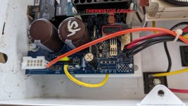
It looks like your thermistor is cracked. Replace it.

Take your cell into a Pool Store that tests Hayward cells and have it tested.
 
I had seen the advice to replace thermistor on many posts. I just wanted to be sure I was going through the troubleshooting steps and making the right repair before committing to replacement. The bench testing done last week seemed not to point there ... but the strange behavior this morning seems to point back there.

How does a bad thermistor affect the voltage between RED and WHT inputs? The reason I ask is that the operating voltages on the display have always been outside the documented ranges yet Cl was reliably produced... Until the failure in July. So, does that point to a possible additional issue to consider?

If nothing else to consider first, I'll proceed with thermistor replacement. I have a replacement thermistor and a new soldering kit ready to go. I had some experience with soldering back in college, 30 yrs ago, but not much since. "I know enough to be dangerous."

Thanks.
 
How does a bad thermistor affect the voltage between RED and WHT inputs? The reason I ask is that the operating voltages on the display have always been outside the documented ranges yet Cl was reliably produced... Until the failure in July. So, does that point to a possible additional issue to consider?

None of us know the circuits of the board well enough to say.
 
  • Like
Reactions: ChasPro
Got lucky that the unit was misbehaving on the bench today. Check out what happens when you squeeze a thermistor ...

NOTE: Don't use your hand if the unit has been on for a while ... the thermistor gets too hot to touch under normal operating conditions. Others have shown use of a large clip to squeeze the thermistor.

Letting the unit sit plugged in for a couple of minutes, the voltage started to drift down (pic with 24.3v), then squeezing the thermistor it gradually returns to 30.3v. After letting go, V sits there for about 20 seconds and then starts to drift down again slowly, repeat ... just for the fun of it.

OK. Now I'm convinced. Not that I didn't trust you guys... I'm an engineer so it was either "prove it through experimentation", or "Turn off your Nav computer, Luke." I was willing to go either way ... this just sits better for me.

P.S. I have the full 2 min video, but the site wouldn't let me upload. Maybe there's another way to share on the site.
 

Attachments

  • PXL_20230814_221201114.TS_exported_14046.jpg
    PXL_20230814_221201114.TS_exported_14046.jpg
    337.3 KB · Views: 3
  • PXL_20230814_221201114.TS_exported_5509.jpg
    PXL_20230814_221201114.TS_exported_5509.jpg
    356.8 KB · Views: 3
OK. Now I'm convinced. Not that I didn't trust you guys... I'm an engineer so it was either "prove it through experimentation", or "Turn off your Nav computer, Luke." I was willing to go either way ... this just sits better for me.

Would we steer you wrong? :goodjob:
 

Enjoying this content?

Support TFP with a donation.

Give Support
Would we steer you wrong? :goodjob:
Well, the Hayward diagnostic guide also said to test the transform output blue/white and grey/violet pairs for resistance... and, unless I'm doing that wrong, they were both 0 instead of the 2-3 ohms expected ... so it could [also] be a transformer. TBD. Thermistor first.
 
Success. I chose to remove/replace the thermistor instead of snipping off and soldering to the existing leads. I made sure to have a soldering iron with enough power to heat and melt the existing solder in the larger heat-sinking pads. I bought a soldering kit ... but found that the provided flux was not compatible with PBC electronics (some are acidic and if not properly cleaned off will eat away at the board). The main issue I had while installing the new thermistor was the thin solder, as it flexed too easily. I would use heavier solder next time so that when pressing into position to melt, it would not drift away. The results with the thin solder and very little recent practice are a little rough, yet I'm hoping solid enough to last over time with repeated hearing and cooling of the board through normal use.

I installed last week, and ran it for several days while it was cooler outside. Today we are in the 80s with direct sun on the cabinet ... seems to be running fine.

See some pictures attached.

I guess that's it ... solved! Thanks.
 

Attachments

  • PXL_20230820_221800881.jpg
    PXL_20230820_221800881.jpg
    364.2 KB · Views: 2
  • PXL_20230820_222111656.jpg
    PXL_20230820_222111656.jpg
    242.5 KB · Views: 2
  • PXL_20230820_222156314.jpg
    PXL_20230820_222156314.jpg
    169.7 KB · Views: 2
  • PXL_20230820_222445455.jpg
    PXL_20230820_222445455.jpg
    311.3 KB · Views: 2
  • PXL_20230820_224709232.jpg
    PXL_20230820_224709232.jpg
    450 KB · Views: 2
  • PXL_20230820_221728524.jpg
    PXL_20230820_221728524.jpg
    326.6 KB · Views: 2
  • Like
Reactions: JamesW
Thread Status
Hello , This thread has been inactive for over 60 days. New postings here are unlikely to be seen or responded to by other members. For better visibility, consider Starting A New Thread.