Aqualink control panel losing power

Nothing is wrong with your pumps.

What does the other 240V CB power?
heck if I know. I will try to trace the wires tomorrow. It's raining and dark now. I did figure out how to cut power to that box, and am looking into how I can replace the CB's. I am guessing I should replace all three, while I'm at it. but maybe I'll start with just one.
 
No reason to replace all 3 CBs.
Your signature indicates you have a waterfall, is there a separate pump for the waterfall? If so then very likely that's what the other 240V breaker is for.

If that were the case I would move the cleaner pump power to share the CB with the waterfall pump and not run the other CB so close to its maximum loading.

You will never run the cleaner and the waterfall pumps at the same time.
 
  • Like
Reactions: NewPoolGirlTX
I would only replace the breaker that is tripping, and it should be replaced with a GFCI breaker. Your signature indicates you have a waterfall, is there a separate pump for the waterfall? If so then very likely that's what the other 240V breaker is for.
yes, I have a separate waterfall pump. the only other thing we have is lights, and the spa
 
No reason to replace all 3 CBs.


If that were the case I would move the cleaner pump power to share the CB with the waterfall pump and not run the other CB so close to its maximum loading.

You will never run the cleaner and the waterfall pumps at the same time.
Oh that's a good idea. I will have to see if I can figure out how to do that! So move the cleaner pump to be with the waterfall pump and replace both with GFCI's?

I am a complete idiot about most of this, but I love to learn and am a DIYer when I can. Thank you!!
 
Do you have automation? Typically we see a cleaner pump on the same circuit as the filter pump because the cleaner's timer is wired in series with the timer for the filter pump so that there is no chance of the cleaner pump running unless the filter pump is also. If that is the case there isn't an easy way to move the cleaner pump to the other circuit.
 

Enjoying this content?

Support TFP with a donation.

Give Support
Do you have automation? Typically we see a cleaner pump on the same circuit as the filter pump because the cleaner's timer is wired in series with the timer for the filter pump so that there is no chance of the cleaner pump running unless the filter pump is also. If that is the case there isn't an easy way to move the cleaner pump to the other circuit.

Her profile shows Jandy Aqualink automation which will only run the cleaner pump when the filter pump is running.
 
Her profile shows Jandy Aqualink automation which will only run the cleaner pump when the filter pump is running.
Ah of course I should gone back and looked at the pictures.
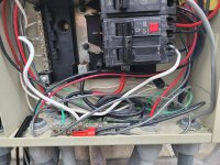
So to move the cleaner to the other circuit it looks like it just a matter of disconnecting the two short jumpers the feed the line side of R2 from the load side of R1, and connecting them in parallel with the LINE side of R3 (which I'm guessing controls the waterfall pump and is fed by the other 2-pole breaker).
 
Well, here's what I've done. If one of y'all can look at it and LMK what you think, I'd love it. (I'm scared to turn the power back on:ROFLMAO: hoping for feedback before I do)

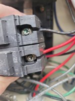
First pic is how the old one was wired.
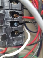
Second pic is how I wired the new one. (so I used the brass colored one and left the gold one empty)
Then I connected the white wire that is attached to the breaker to the left side row where the other whites are connected. Last pic

What do you think? Should I turn everything on and see what happens?? :mrgreen:
20231110_162356.jpg
20231110_164041.jpg20231110_164045.jpg
 
Last edited:
The RED and BLACK wires from the pump should both be connected to the outside terminals. The middle terminal is for NEUTRAL only. Your pump does not have neutral.
 
  • Like
Reactions: NewPoolGirlTX
The RED and BLACK wires from the pump should both be connected to the outside terminals. The middle terminal is for NEUTRAL only. Your pump does not have neutral.
really? Crud,I thought silver was neutral.

So if I move the black wire to the gold screw, I should be ok?

Nothing goes to the silver screw?

Do I have the white wire correctly set on that lefthand side of neutral screws?

THANK YOU. this is why I asked before turning it all on. ;):oops::eek:
 
really? Crud,I thought silver was neutral.

So if I move the black wire to the gold screw, I should be ok?

Nothing goes to the silver screw?

Do I have the white wire correctly set on that lefthand side of neutral screws?

THANK YOU. this is why I asked before turning it all on. ;):oops::eek:
The N on the middle screw indicates NEUTRAL. The white wire from the GFCI CB goes to the bar which looks correct.
The 2 outside screws are the Power connections and with a 240V pump - a wire goes to each side.
 
  • Like
Reactions: NewPoolGirlTX
The N on the middle screw indicates NEUTRAL. The white wire from the GFCI CB goes to the bar which looks correct.
The 2 outside screws are the Power connections and with a 240V pump - a wire goes to each side.
Appreciate this so much
Off to fix it and turn it on

Good news is it is on the outside of my detached garage so if it explodes or starts a fire, my house should be safe

Can't thank you enough!!
 
The RED and BLACK wires from the pump should both be connected to the outside terminals. The middle terminal is for NEUTRAL only. Your pump does not have neutral.
UGH!!! that did not work. I changed the black wire to the gold screw. When I turn it all on, i get a flash of power on the board and then nothing.

Crud. I am defeated.

I can't do more tonight due to dark and wet. Any and all suggestions for next steps are appreciated.

Heavy sigh.
 
So this new GFCI CB would only provide power the pump. Looking back at the other posts and correspondence, it was indicated that the actual control board is powered by 120V which would be that single CB on the left side.

There was also a discussion about use the meter to verify voltage on each of the terminals to confirm which was 240V and which was 120V.
 
So this new GFCI CB would only provide power the pump. Looking back at the other posts and correspondence, it was indicated that the actual control board is powered by 120V which would be that single CB on the left side.

No, the control board is being powered by a pickoff from one leg of the 240V pump circuit.

And then the neutral for the control board transformer is going to the neutral bar.

Now with the GFCI CB that neutral from the control board transformer needs to go to the middle N screw on the GFCI CB.

The GFCI CB, as it is currently wired, has an imbalance between the legs causing a GFCI trip.
 
Last edited:
  • Like
Reactions: NewPoolGirlTX

Enjoying this content?

Support TFP with a donation.

Give Support
Thread Status
Hello , This thread has been inactive for over 60 days. New postings here are unlikely to be seen or responded to by other members. For better visibility, consider Starting A New Thread.