Aqua Logic Transformer

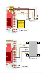
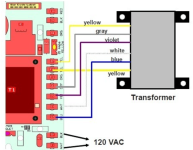
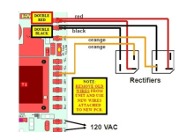
I've bene spending time learning the technical side of the pool equipment. I had a question about the transformer and the two rectifiers. Based on the pictures below, the transformer has two output wires (K - Both Yellow) (to get 24 VAC), but 4 input wires of 120 VAC (H - Gray, Violet, White and Blue). Why does the transformer need 4 inputs of 120 VAC?

Also based on the pictures below. Two Orange Wires (J) with 24 VAC are going to the rectifiers, one to each rectifier. Red and black are coming back from the rectifiers with 18-33 VDC and red and black are connected to each other. Can anyone explain how this circuit works. I understand that rectifiers use diodes to convert AC to DC, but then why use two rectifiers and why are red and black connected to each other and also why do the two orange go to separate rectifiers (assuming one orange wire is hot and one orange wire is neutral with 24 VAC)?
 

Attachments

  • Rectifier and Transformer Wiring Instructions.jpg
    Rectifier and Transformer Wiring Instructions.jpg
    76.8 KB · Views: 6
  • ProLogic Main PCB Layout.jpg
    ProLogic Main PCB Layout.jpg
    314.7 KB · Views: 6
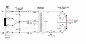
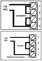
The transformer has two sets of primary windings so that it can take an input of 120 volts or 240 volts.

For 120 volts, the windings are in parallel and for 240 volts, the windings are in series, which gives each winding 120 volts because, in series, the voltage is divided.
 
I've bene spending time learning the technical side of the pool equipment. I had a question about the transformer and the two rectifiers. Based on the pictures below, the transformer has two output wires (K - Both Yellow) (to get 24 VAC), but 4 input wires of 120 VAC (H - Gray, Violet, White and Blue). Why does the transformer need 4 inputs of 120 VAC?

The transformer can be wired for 120V in or 240V in. The other wires are used with a 240V connection.
Also based on the pictures below. Two Orange Wires (J) with 24 VAC are going to the rectifiers, one to each rectifier. Red and black are coming back from the rectifiers with 18-33 VDC and red and black are connected to each other. Can anyone explain how this circuit works. I understand that rectifiers use diodes to convert AC to DC, but then why use two rectifiers and why are red and black connected to each other and also why do the two orange go to separate rectifiers (assuming one orange wire is hot and one orange wire is neutral with 24 VAC)?
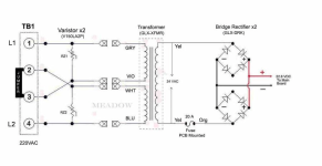
AC alternates positive and negative. To transform it to DC you need one rectifier when negative and one when positive.
 
1707433572918.png

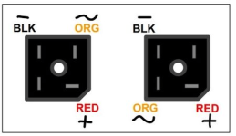
The Red wires go on the + terminals, which are the terminals that are turned relative to the other three and sometimes are marked by a cut corner.

The black wires go on the opposite terminals, which are the (-) terminal of the DC.

The yellow or orange are the AC from the transformer.

1707433648151.png
 
I would love to see the engineer's explanation for why there are two bridge rectifiers and they are only using 1/2 of each. I could hazard a guess that they ran into heat dissipation limits on the part, but if that is the case surely it would cheaper to use a single larger part and/or a better heatsink.
 
  • Like
Reactions: JamesW
By changing the jumpers, the transformer can take 120 or 240 volts.

In the below picture, it is set for 240 volts and the windings are in series.

If you change the jumpers, it can take 120 volts because the windings are in parallel.

The AquaLogic and ProLogic are set up for 120 volts only and the jumpers are only used on the Aquarite.

You can "theoretically" use 240 for the Prologic by wiring directly, but this is not something you should do unless you understand everything about the wiring and even then, probably not a good idea.


1707578331354.png

1707578360309.png
 
Last edited: