Pentair IC60 and Easytouch8-SWG cycling on/off

Did your IPH come with the Stenner pump head or did you replace it?

- - - Updated - - -

Speaker wire!?!?

Hey, I said it was a hack! I thought that agreeing to post meant I had immunity from ridicule! :).


Yes speaker wire. Made it easy to make sure I got plus and minus right on the DC, and it is 12 GA, so plenty of copper to carry 7 amps.


I dont don't know how to tell if my iPH is or is not a Stenner pump, but it is stock. Are you saying it looks like a Stenner? Could Pentair have changed it due to customer complaints?

All I can say after the first two days of the iPH (granted this is just a first impression) is that it is pretty nice. I started it at 50%, and pH is low after 2 days, so I dropped it to 40%. My preference is for it to slowly creep up so I can hit the button once in a while to knock it back. My guess is, I will wind up around 30%.

Anybeasy way to determine the pump type?
 
xyz,

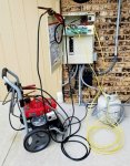
It appears to me you left something out... After talking to one of my old contacts at the NSA, he provided me with the following High Resolution Satellite image of your "modification"...

Looks like you left out your hack was powered by Propane.. :kim:


xyz Hack 2.jpg

Jim R.
 
Ok, maybe I don't feel as bad :)

Too funny!


on a more serious note, I think you have the newer box layout, and so you have space to the righ lower area, and this switcher will fit there with space behind and in front to allow the fan to move air.

Having said that, you seem to want to run at lower SWG percentages, so it will run cool and is bet the fan won't even come on.
 
Ok, so here is how to wire up the power supply


1AC0BFFB-C4F5-4C82-A7AE-23C58E65664C_zpscnjmoffw.jpg
 
If you didn't touch your IPH then you have the newer version that uses the Stenner pump head. The older models used a Shurflo pump which isn't nearly as nice as yours. I looked for the replacement head like yours but it looks like they want $350 for it. I'll buy a complete Stenner for that price and it won't require any backwoods electrical ingenuity.
 
L is line, N is neutral. This is where you hook up your 240 (in my case because I have a 240vAC pump) that came from the pump relay in the previous picture.

Then in run a ground wire to the grounding terminal along the bottom of the box. Let the 36vDC float so it can be referenced to the existing power board.

Then em wire the black wire from the plug on the power board to the "-V" and leave it connected to the plug. You can solder onto the wire, use a wire tap, or cut, and wire nut the (now) 2 wires with the wire coming from the "-V" terminal on the switcher.
 
If you didn't touch your IPH then you have the newer version that uses the Stenner pump head. The older models used a Shurflo pump which isn't nearly as nice as yours. I looked for the replacement head like yours but it looks like they want $350 for it. I'll buy a complete Stenner for that price and it won't require any backwoods electrical ingenuity.

That is totally cool info--more good news!

Makes sense. If by backwoods mod, you mean this one, this issue, and this mod is not associated with the iPH. It is the IC60 being somewhat incompatible with my older version of the easytouch8. With or without the iPH, the issue exists. And I definitely do like the controller that has no discernible effect on this IC60 issue, with the exception that when the SWG was failing, the iPH didn't dose, which is by design.

Bottom line, if your IC works well with your current easy touch, I have confidence it will work well with an iPH. I could see a design that is run off the pump and then another relay with a timer, but the iPH is plug it in and it works. And now that I know it has a Stenner, I'm much happier--so thanks! I was a bit disappointed that I would need more rework next year.

And based on your other posts, I was going to upgrade to a Stenner next year. Now I don't have to! And something is wrong if the pump costs 350c and the iPH cost 450, that is a pretty cheap controller and container. And I like the container feature where you dump a sealed MA bottol on it and it opens the seal for you. No splashing and minimal fumes.

Yea!

- - - Updated - - -

I just realized, based on the iPH already being a Stenner, I think I'm done! Well I will need to clean up the internal and external wiring, and install the new IC60 from Pentair when it arrives.

My my remainjng decision is--do I keep after Pentair to really fix the issue for the betterment of all? Because based on some of y'all's posts, it will still reboot even with the new firmware.

OR...

Do I leave it alone, now that I have a rock solid power supply?
 
Pentair IntelliChem External Pump 751000610 | Pentair 751000610 | Stenner 45MP2

That's your pump head

IntelliPH pump head - Google Search

That's mine.

I don't recall having any issues with my IC prior to installing the IPH. Either way if this fixes it then I'm halfway home.

holy smokes! More than double the price!

My my guess is that this issue is dependent on numerous factors. I -think- we narrowed it down to the spike when you jump from 36-42vDC.

If you pull your iPH and dial it back to 5%, does that make it worse? The tech at Pentair seemed to have some folklore with respect to it being worse at low setting and better at high settings, so you may be seeing this effect vs with/without iPH?

Maybe you are not as close to the hairy edge as I am; maybe a 10,000 mfd cap will do the trick? Worth a try. But this PS mod has me smiling every time I walk by and see green green green green LEDs. A 100v 10,000mfd cap is only a few bucks...
 

Enjoying this content?

Support TFP with a donation.

Give Support
Ah, and I just realized, I forgot to talk about the +V DC out from the switcher.

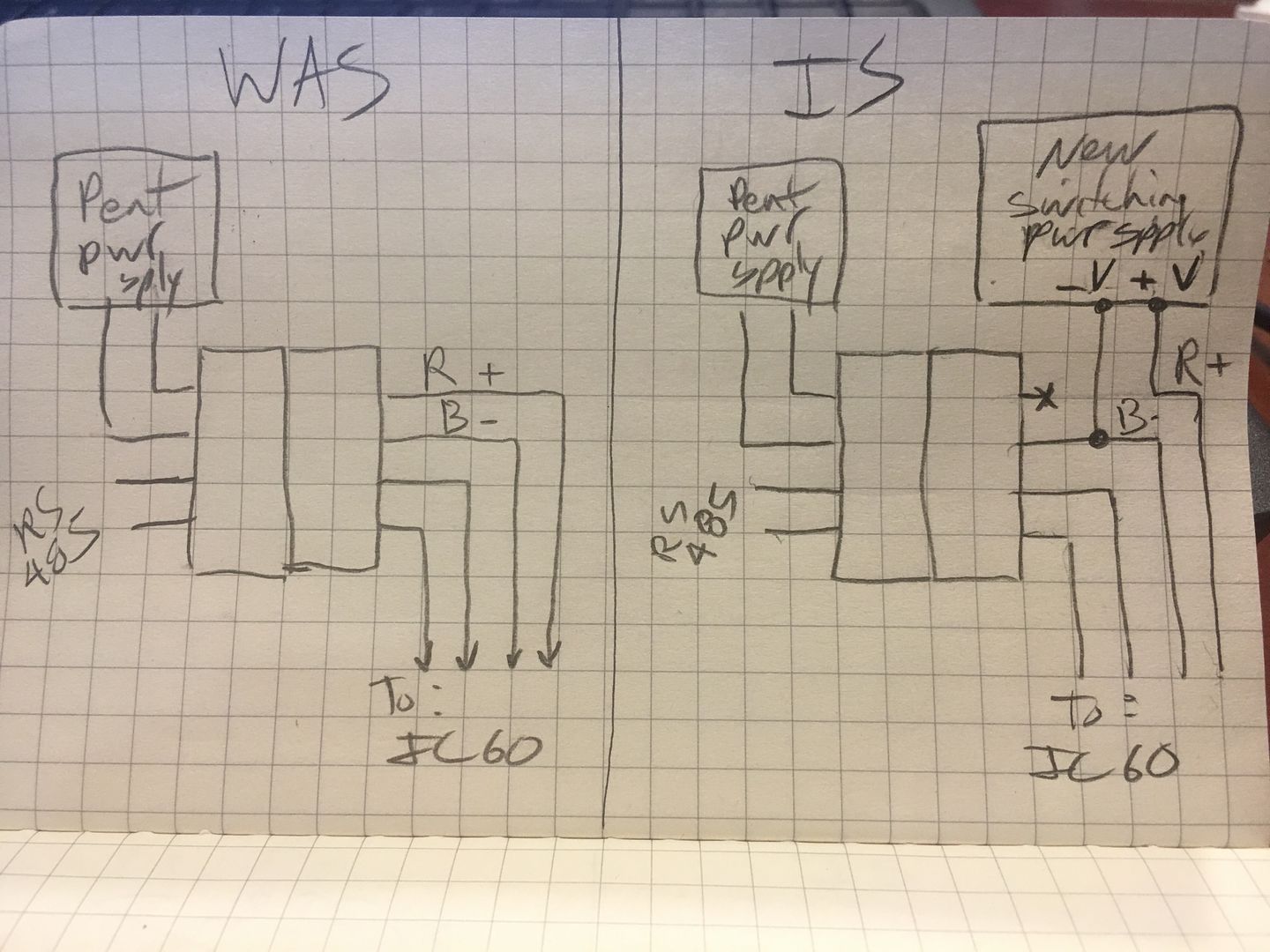
You want to lift/remove the red wire from the IC plug. You need to disconnect it. Do not connect the new switching power supply +V to the Pentair power supply red connection.

These plugs are bayonet-ish, in that there are little prongs in the connector. If you have very small thin screwdrivers or don't mind clipping the plastic portion of the plug, then you can reverse the mod. Anyway, figure out how to kee the 3 wires connected, and disconnect the red wire--this red wire now gets driven by the new switcher.

I found male and female versions of these connectors and then soldered jumpers for the 3 that remain connected (I.e., the RS485 and the black -V), and then pulled the red wire out with a single wire that then gets driven by the switcher (+V).
 
I don't fully understand the hook up after the power supply. Got a picture of that? I'll even use speaker wire since it looks like that's what all the cool guys are doing

Do you mean the connection to the connection to the IC control board/plastic connector? If yes, I will try to remember to take a pic tonight when I get home.

- - - Updated - - -

Or maybe it is that I needed to post that last replay about the red wire connection to the +V.

Either way, I'll try to remember tonight.
 
Then in run a ground wire to the grounding terminal along the bottom of the box. Let the 36vDC float so it can be referenced to the existing power board.

Then em wire the black wire from the plug on the power board to the "-V" and leave it connected to the plug. You can solder onto the wire, use a wire tap, or cut, and wire nut the (now) 2 wires with the wire coming from the "-V" terminal on the switcher.


Ok.. I've changed my mind.. you would make a great Pentair Tech Writer... I suggest you send them a copy of this and I suspect that they will fly you out for an interview tomorrow. :)

Since I don't speak "Pentair" , can you please tell us in English what goes where?

I understand the AC and ground connections to the new power supply. What I don't understand is how you wired the Red and Black wires at the EasyTouch SWG connector.

I "assume" the connector is left connected to the EasyTouch PCB.
I "assume" the Black wire is now connected through the connector to the ET PCB and is also connected to the -V output of the new Power Supply.
I "assume" the Red wire is no longer connected through the connector to the ET PCB but is now connected to the +V output of the new Power Supply.

Are my assumptions correct?

Thanks,

Jim R.


You got it!

Hopefully I can get a picture tonight.

The he concept is to keep the ground and -V (DC) all connected and referenced to the same black/neutral as it always was.

Then em drive the positive out (red wire) to the chlorinate with the new output from the new power supply.

Sorry about the confusion, it is a tad tricky.

oh and I see some of my typing was somehow autocorrected to weird stuff, so I'll fix that too. Stand by...
 

Enjoying this content?

Support TFP with a donation.

Give Support
Thread Status
Hello , This thread has been inactive for over 60 days. New postings here are unlikely to be seen or responded to by other members. For better visibility, consider Starting A New Thread.