- Jun 7, 2017
- 9,192
- Pool Size
- 29000
- Surface
- Plaster
- Chlorine
- Salt Water Generator
- SWG Type
- Jandy Aquapure 1400
Sorry all, still getting used to this forum and I missed a few posts...
HermanTX: Thanks, this is where I was struggling. Tell me which wires go where and I am good, lol.
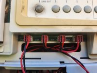
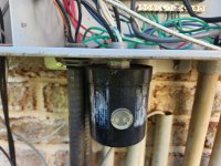
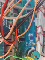
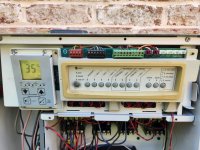
Here are pics of my system:
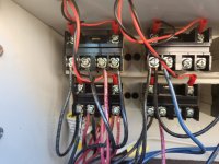
These are your relays. One of these, probably the top left, goes to your pump. Do you know which one for sure? The two wires coming out of the top of the relay and into the panel above (you can remove that one too) go to that other pic we posted above.
Do you have 2 pumps? Looking at this it the top left relay and the relay below that are wired together. It could be the SWG though as those are usually wired together.