- May 17, 2013
- 23
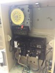
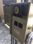
Hello, I'm looking to replace my Intermatic Control panel with a slightly different model Intermatic control panel. I chose to use a single timer since I removed a booster pump. I want to make several changes in the process and created a couple of diagrams to help illustrate. If the attachments don't work, please refer to the links for the full diagrams.
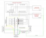
Existing Diagram - (Link for large image)
Proposed Diagram - (Link for large image)
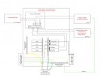
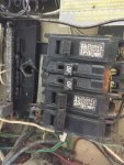
Q1. Circuit Breakers configurations - 60 Amp feed from Main power panel; 110 Amp total on sub-panel. To help reduce the total amps on the sub-panel, I'm thinking of the following:
Slot 1: 30A single pole -> replace with a 20A single pole; supports GFCI outlet, which is rarely ever used
Slot 2: tandem 20A -> replace with a single 20A single pole; supports 2 LED pool lights
Slots 3/4: 20A double pole -> replace with 20A double pole with GFCI; supports the pool pump at 10.9 amps
Any thoughts on this setup?
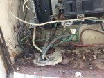
Q2. THWN wires from the power source looks like it slightly melted/burned at one point (1-2" of sheathing). What is the best way to handle this?
Q3. New Circupool RJ45 SWG will connect to the timer on terminals #2, #4 (load #1 and load #2 on the Intematic timer). It will share the double pole 20 Amp circuit breaker with the pool pump and gas heater. I can't find the max amp draw from the gas heater, but I can't imagine it being high. Will it be ok to run the SWG, pump, and gas heater on the same circuit?
Existing Diagram - (Link for large image)

Proposed Diagram - (Link for large image)

Q1. Circuit Breakers configurations - 60 Amp feed from Main power panel; 110 Amp total on sub-panel. To help reduce the total amps on the sub-panel, I'm thinking of the following:
Slot 1: 30A single pole -> replace with a 20A single pole; supports GFCI outlet, which is rarely ever used
Slot 2: tandem 20A -> replace with a single 20A single pole; supports 2 LED pool lights
Slots 3/4: 20A double pole -> replace with 20A double pole with GFCI; supports the pool pump at 10.9 amps
Any thoughts on this setup?
Q2. THWN wires from the power source looks like it slightly melted/burned at one point (1-2" of sheathing). What is the best way to handle this?
Q3. New Circupool RJ45 SWG will connect to the timer on terminals #2, #4 (load #1 and load #2 on the Intematic timer). It will share the double pole 20 Amp circuit breaker with the pool pump and gas heater. I can't find the max amp draw from the gas heater, but I can't imagine it being high. Will it be ok to run the SWG, pump, and gas heater on the same circuit?
Last edited:


