Repair AQL-TB-RF-PS-8 Remote LCD Screen or Buy Used

Sneaky D

Well-known member
Aug 2, 2019
50
Gilbert, AZ
Pool Size
25000
Surface
Plaster
Chlorine
Salt Water Generator
SWG Type
Hayward Aqua Rite (T-15)
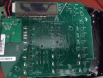
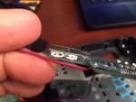
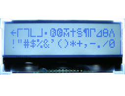
Still trying to get all the problems fixed from the prior owner (Hacks!). I think their kids knocked the remote AQL-TB-RF-PS-8 on the ground and the the LCD screen is cracked. Remote still functions but would be nice if I can read the screen. Anyone got a spare lying around?

I may attempt to repair or send it back for repair. I have a friend in the LCD business so I may use him as a resource. Couldn't find cheaper than $300 on Ebay and new they are crazy expensive. Any ideas?
 

Attachments

  • remote 1.jpg
    remote 1.jpg
    63.7 KB · Views: 7
  • Remote 2.jpg
    Remote 2.jpg
    47.2 KB · Views: 7
Here is the inside of the remote. Didn't see any markings on the screen for a component part#.

Also called Hayward and they weren't much help. Told me to call one of their authorized repair centers but I doubt they do board level troubleshooting there.

Anyone got a spare lying around or even a blown one? I could part out the screen. Likely the same screen on the remote and the control module.
 

Attachments

  • board 3.jpg
    board 3.jpg
    96 KB · Views: 6
  • board 4.jpg
    board 4.jpg
    91.9 KB · Views: 6
  • board 5.jpg
    board 5.jpg
    89.8 KB · Views: 9
  • board 6.jpg
    board 6.jpg
    47.2 KB · Views: 7
I can't really be sure but that looks like it could be a standard pinout 16x2 line LCD. It's a COG, or "Chip On Glass" form factor rather than the more common modules, but they're still readily available and probably all share a similar pinout.

This is just an example I found online... it's got the standard 14 pins like yours and it's a "parallel" lcd rather than I2C or SPI which have fewer pins.

If you're going to try and get a replacement, you've got to make sure it's the same operating voltage, which shouldn't be too hard to figure out - pin 3 is usually the supply pin and should be 3.3 or 5 volts (or somewhere in between).

The other thing I can't tell is if the backlight is integrated into your display or if it's a separate component but just placed underneath (the backlight is powered by the two pins on the side labeled A/K)

Hope that helps!
 
  • Like
Reactions: Sneaky D
I can't really be sure but that looks like it could be a standard pinout 16x2 line LCD. It's a COG, or "Chip On Glass" form factor rather than the more common modules, but they're still readily available and probably all share a similar pinout.

This is just an example I found online... it's got the standard 14 pins like yours and it's a "parallel" lcd rather than I2C or SPI which have fewer pins.

If you're going to try and get a replacement, you've got to make sure it's the same operating voltage, which shouldn't be too hard to figure out - pin 3 is usually the supply pin and should be 3.3 or 5 volts (or somewhere in between).

The other thing I can't tell is if the backlight is integrated into your display or if it's a separate component but just placed underneath (the backlight is powered by the two pins on the side labeled A/K)

Hope that helps!
Dang that looks like a pretty close match. K and A Aren't on the side like mine but still pretty close. I'm debating if I should desolder the LCD and see if there is any component markings that might get me closer to the correct part. I think you may be correct about COG. If I get some time maybe I'll measure the voltage on pin 3 to see what I get.
 
I took another look and this may not have a standard pinout... these things do vary per manufacturer, but with a meter you should be able to figure out what it's being supplied with easily enough. I can't quite zoom in enough, but in your "board 5" photo it looks like pin 12 might be a ground or something - based on the fact that it's a thicker trace and looks to be connected to all the LEDs.

It is also still possible that it's using SPI or I2C and isn't a parallel/8-bit device. You'll learn more if you take it off and can see the pcb traces at least - and maybe a part number at best. If you do remote it, it's probably easiest to carefully cut all the pins - to free up the lcd - and then desolder the pins 1 at a time.
 
Thread Status
Hello , This thread has been inactive for over 60 days. New postings here are unlikely to be seen or responded to by other members. For better visibility, consider Starting A New Thread.