I am in the market for a new pump and was looking at a two speed. I was thinking there would simply be a switch on the motor to switch from fast to slow. After some research it sounds like there is a little more to it so I don’t think I will be doing that. I don’t want to replace timers and add wires etc. Doing this research however, got me thinking about how mine is wired.
Pool pump originally wired in the 70s but 7 years ago the electrical was all updated inside the house but I don’t think the electrician changed anything on the outside of the house. The point is there are no aluminum wires or old fashioned fuse boxes or anything like that.
Inside the breaker box in the basement there are two 20 amp circuits dedicated to the pool pump. These do not have GFCI protection. Next to the breaker box there is a mechanical timer for the pump. One cable goes from the breaker box into the timer and another from the timer to the pool equipment. The neutral (white) wires are covered in black electrical tape which I understand that indicates they are actually hot. The timer also has some all-white jumper wires.
Outside where the wires come out of the house there is a standard GFCI outlet that does not work. I don’t remember ever plugging anything into it but the reset button never reset the outlet which I just ignored because I never used it. The only time I would ever want to use it I would have the power shut-off anyhow.
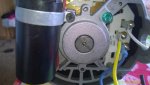
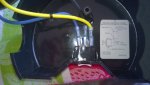
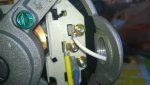
From there the wires go to a covered double pole switch and then to the motor.
From some research I done on this site I am sensing something is not right even beyond the receptacle that will not reset the GFIC. Before I wire up a new pump I want this right.
I am thinking what needs to happen is first replace the 2 separate 20 amp breakers with a double pole with 2 -20 amps and GFCi protection. (Over $100). I seen a few videos on how to install the new breaker but they always go from a single pole to single pole or double pole to double pole. I would be going from two single poles to one double poles. The other oddity is I would not have a neutral (white) wire. Do I connect the white wire from the new circuit to the neutral bus bar anyhow?
Assuming I get that installed moving to the outside the house the cable will have two hots and a ground. Can I even hook up the outlet? Seems like any outlet would require one hot and one neutral and the ground.
Could I be overthinking this whole thing and all I really need to do is replace the non-working receptacle with a new one and if I wired everything exactly the same way I would get the GFCI protection I would need?
One other thing the pump was attached to a separate ground buried in the ground. Is that because the pump was originally installed before houses were grounded the way they are now? Should I continue to use that or should I use the ground coming out of the cable.
I am trying to figure out as much as I can before I open anything up or buy anything.
Pool pump originally wired in the 70s but 7 years ago the electrical was all updated inside the house but I don’t think the electrician changed anything on the outside of the house. The point is there are no aluminum wires or old fashioned fuse boxes or anything like that.
Inside the breaker box in the basement there are two 20 amp circuits dedicated to the pool pump. These do not have GFCI protection. Next to the breaker box there is a mechanical timer for the pump. One cable goes from the breaker box into the timer and another from the timer to the pool equipment. The neutral (white) wires are covered in black electrical tape which I understand that indicates they are actually hot. The timer also has some all-white jumper wires.
Outside where the wires come out of the house there is a standard GFCI outlet that does not work. I don’t remember ever plugging anything into it but the reset button never reset the outlet which I just ignored because I never used it. The only time I would ever want to use it I would have the power shut-off anyhow.
From there the wires go to a covered double pole switch and then to the motor.
From some research I done on this site I am sensing something is not right even beyond the receptacle that will not reset the GFIC. Before I wire up a new pump I want this right.
I am thinking what needs to happen is first replace the 2 separate 20 amp breakers with a double pole with 2 -20 amps and GFCi protection. (Over $100). I seen a few videos on how to install the new breaker but they always go from a single pole to single pole or double pole to double pole. I would be going from two single poles to one double poles. The other oddity is I would not have a neutral (white) wire. Do I connect the white wire from the new circuit to the neutral bus bar anyhow?
Assuming I get that installed moving to the outside the house the cable will have two hots and a ground. Can I even hook up the outlet? Seems like any outlet would require one hot and one neutral and the ground.
Could I be overthinking this whole thing and all I really need to do is replace the non-working receptacle with a new one and if I wired everything exactly the same way I would get the GFCI protection I would need?
One other thing the pump was attached to a separate ground buried in the ground. Is that because the pump was originally installed before houses were grounded the way they are now? Should I continue to use that or should I use the ground coming out of the cable.
I am trying to figure out as much as I can before I open anything up or buy anything.