Aquarite - Diagnose & Troubleshoot your own Main Board

Meadow

0
Jun 10, 2016
477
Temecula, CA
So I just had this opportunity to replace a bad thermistor on the AQR board and would like to share the easy way on how to diagnose a faulty thermistor. First off, the board that I worked on belongs to a friend who doesn’t really know how to solder. So I came up with the idea of using a screw terminal (Digi-Key part# ED2561-ND) to mount the thermistor on. This should enable him to replace the thermistor in the future without having to solder. The original thermistor is AS32 2R025 which has a wider lead wire footprint but the available replacement on hand is SL32 2R025. The latter has a high failure rate due to overheating compare to the AS32. If your PCB footprint can accommodate both types, then you will be far better off using the AS32.

As observed, the thermistor solder pads are larger with multiple through holes to absorb the heat being emitted by the thermistor during normal operation. I had to bump the solder tip temp to 1200°F for this mod. I removed the plastic sleeves and positioned the screw terminals to accommodate both types of thermistors.
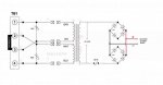
20180704_191734_A.jpg


Good Thermistor:
If the thermistor is good, the voltage reading on the display matches the measured voltage from the thermistor lead farthest from the Red terminal on the board as shown. Make sure the Blk test lead is on the Negative side (not Ground) which is the black terminal or to the R15 (.015 Ω) link as shown in the pic.

20180704_190055_B.jpg


Bad Thermistor:
The thermistor was intentionally removed to simulate or replicate a bad thermistor for this purpose. The measured voltage and the voltage reading on the display did not match the voltage reading across the Blk and Red terminals.

20180704_190342_c.jpg 20180704_190517_d.jpg

Hayward Aquarite vs SwimPure Plus PCB:
The Swimpure Plus model used Cantherm MF73T-1, 2Ω@18A, Ø20mm thermistor. As observed, I can touch and hold the thermistor on my SWP like forever during normal operation without getting burned. You may notice, the SWP board has an extra 24VDC relay labeled as “K4”. I have yet to dig deeper on that!
OTOH, do not dare to touch the SL32 or the AS32 series Thermistors when chlorinating, or you’re gonna swear by it. You’ve been warned, Thermistors on the AQR’s do overheat and too hot to touch. Unfortunately, I misplaced my handheld IR thermometer to give you the numbers. Also, the oil from our skin will adhere to the thermistor making it more susceptible to premature failures.
Personal Conclusion: If your Hayward SWCG has the PCB as shown on the right-hand side below then you will probably enjoy many years of chlorinating without having to replace the thermistor. Hence my vote, hands down!

20180704_184556_e.jpg
 
Last edited:
Re: Aquarite - Low Voltage Power Supply, MOV's are useless or are they?

Below is the Hayward Aquarite Low Voltage schematic diagram for those in the need to know.

There are two V150LA2P, VARISTOR 240V 1.2KA, made by LittelFuse as the primary line of defense against transient or voltage spike. They are connected in series, across L1 & L2 when configured for the 220V operation. Alternatively, the two are in parallel across L1 & Neutral for the 120V configuration. If the AC power is applied to TB1, the MOV's are "HOT" and susceptible to voltage spike even if the inductance Transformer and any of its wire is loose or not properly connected to the board. And no way, for any downstream components to induce voltage spike or sags back to the MOV's.

Bottom line is, nothing in the mainboard is likely to induce damage to the MOV's except for the incoming AC!

MOVs are often connected in series with a thermal or line-fuse, so that the fuse disconnects before catastrophic failure can happen. The initial failure mode of an MOV is always a short circuit in an attempt to limit the voltage supplied to an electric device by either blocking or shorting to ground any unwanted voltages above a safe threshold. And that is why it should be preceded by a series fuse. If the fuse isn't there and there's enough energy available to cause the MOV to melt/explode the final failure mode will be an open and the downstream circuitry will then be subjected to the transient causing the open or to future transients which will then cause questions to be asked about whether the downstream circuitry will fail open or shorted. MOV's have a finite life expectancy and "degrade" when exposed to a few large transients, or many small transients. As a MOV degrades, its triggering voltage falls lower and lower.

As to the AQR board, Hayward disregarded the line fuse before the MOV's. The upstream local circuit breaker has no function related to disconnecting an MOV. So what's the MOV in the AQR board for and how are they going to protect your main board? Well, it's more like of a visual notification for me! If it torched itself and went up in smoke then that's a good indication that the MOV took the hit. The AQR will continue to chlorinate even with all the smoke and fire going on until the MOV's vaporized and you may not even notice anything unusual until the next time you inspect the board.
 

Attachments

  • AQR Low Voltage Power Supply.jpg
    AQR Low Voltage Power Supply.jpg
    32.1 KB · Views: 419
Re: Aquarite - In Depth Sub-Sectional onboard Power Supply

Giving this a bump for those Electronic Enthusiasts willing to revive those dead AQR main board.

Use the Negative Black Terminal or the R15 (.015Ω) metal jumper on the board when measuring TP Voltage as shown in the below pic. Test points are accessible with the Display bd in place.
Measure the voltage in the following order from 1-5. You cannot have Voltage reading on TP-2, 3, 4, & 5 if TP-1 is out, no reading on TP-3 if TP-2 is out, and so on... refer to the below Schematic Diagram to analyze the Voltage distribution path.

20180704_191632_b.jpg

AQR sub-sectional onboard Power Supply Schematic Diagram. The marking code on the U13 is unreadable hence, my wild guess! Please correct me if I'm wrong!

Power Distribution_b.jpg
 
Re: Aquarite - Diagnose & Troubleshoot your own Main Board

This is excellent information. Thank you. Its been 20 years since I was in the USAF as Precision Measurement Equipment Journeyman, but I still think I can solder!

Let me ask, what are the symptoms of a bad thermistor? Is the only way to tell with the readings above? Or what would prompt someone to check the thermistor in the first place?

- - - Updated - - -

Also, if this is a common problem, perhaps we can start a repair service to fix these boards for fellow members at a reasonable price. :)
 
Re: Aquarite - Diagnose & Troubleshoot your own Main Board

This is excellent information. Thank you. Its been 20 years since I was in the USAF as Precision Measurement Equipment Journeyman, but I still think I can solder!

Let me ask, what are the symptoms of a bad thermistor? Is the only way to tell with the readings above? Or what would prompt someone to check the thermistor in the first place?
Symptoms include no power and chlorinating light, no power to salt cell. Youtube is flooded with good info, google "aquarite board repair"

- - - Updated - - -

Also, if this is a common problem, perhaps we can start a repair service to fix these boards for fellow members at a reasonable price. :)
No, I'm just a hobbyist donating my spare time to this community hoping to give something in return from what I've learned from others. That's what this forum is all about.

There are eBay'ers who offers to repair AQR bd for a price and they also buy & sell mainboards. They also sell those boards that cannot be fixed beyond their ability for a penny. That's how I got mine and I fixed it! :whoot:
 
Re: Aquarite - GLX-PCB-RITE (1.59) and Power Dist Schematic Diagram (Section-B)

Cont'd...
Our Hayward SwimPure Plus SWCG main board has a SPST K4 Relay as shown in the below pic. The original Thermistor on it is made by Cantherm (MF73T-1, 2/18) 20mm dia @ 18A and it does not get warm at all when chlorinating. I would like to assume that the addition of K4 relay is one of the changes implemented on the latest Software ver r1.59 in an effort by Hayward to address the Thermistor issue.

I have analyzed the Voltage flow path and found out that the main function of the K4 relay is to bypass the Thermistor via shunt approach. If the AC power is first turned on, the K4 relay kicks in within a few milliseconds providing an ample time for the In-Rush Current Limiter to do its job as designed. At this point, the Thermistor is relieved from duty until the next power interruption. Having said that, the Thermistor is guaranteed to outlast all other components on the board.

It has come to my attention that not all SwimPure Plus models have the K4 relay. So here’s hoping to hear from other AQR Sw ver r1.59
users to confirm if their mainboard has the K4 Relay.

Tips for you! If you are in the Market for a replacement GLX-PCB-RITE then I would highly recommend for you to pick the board with the K4 Relay as shown in the below picture. Unless you enjoy soldering and stock up on Thermistor.

SWP15.jpg


Here is the missing section of the GLX-PCB-RITE Power Distribution Schematic Diagram to supplement the previous sub-sectional Schematic Diagram I posted above. This concludes the onboard Power Supply Distribution flow path on the board.

The primary function of the SPST K4 Relay is to bypass the Thermistor as described above. Pin# 15 of U5 (MIC5841YN) switches from Hi to Lo state within a few milliseconds after the AC power is turned on. Pin 15 remains Lo until the AC power is turned off. Disregard, the K4 from the drawing if your board does not have it!

OTOH, pin# 15 on the older AQR mainboard has no circuit trace and the output is not assigned. The Micro-Controller chip dictates the switching functions of U5. Presumably, a burned-in Flash and not sure if something my outdated programmer can read. For the skilled tech-savvy, a simple timer would do the trick when upgrading the board.


Attachments

  • Pwr Dist Section-cell.jpg
    Pwr Dist Section-cell.jpg
    44 KB · Views: 308
Last edited:
Are the Aquarite and Swimpure boards interchangeable? Or if replacing a board do you have to stick with the same one?
 
So the boards pictured above are the same except for the thermistor? If ordering a board and the part numbers are the same, how would you know which you are getting?

The OP indicates the Swimpure version should be more reliable.
 
Good question! You can't go wrong as long as your existing mainboard is a GLX-PCB-RITE and replacing it with the same.

Tough one, ask the seller about the software version or make sure the seller is selling the exact model as pictured like this for $199.

Or if you like challenges you can try to bring this reliable bd back to life by following all of the above troubleshooting guidelines. Just make sure you're getting the model as pictured in the ads.

added: GLX-PCB-RITE noticed the K4 relay on it?
 
Last edited:

Enjoying this content?

Support TFP with a donation.

Give Support
What software version would I looked for?

Btw, my Aqua Rite is working fine right now. I’m curious for future reference should I ever need a new board.

My unit was installed in early 2004. In 2009, the main board was replaced (don’t know which of the boards you pictured was put in) and it’s been fine since. The firmware version I have is 1.50.

If I get curious enough I may take a peek and see what’s in there. :)
 
It has come to my attention that not all SwimPure Plus models have the K4 relay. So here’s hoping to hear from other AQR Sw ver r1.59users to confirm if their mainboard has the K4 Relay.

I think the latest GLX-PCB-RITE Sw ver is r1.59. I am quite new into pool ownership and don't know much about the SW updates. Hence, my quote above! Our SWP15 is about 2 years old, Sw Ver r.159.
My knowledge is limited to GLX-PCB-RITE only because that is what I have as a Guinea pig and I have yet to explore the electronic side of the cell if any.

The spare board I'm using to post images on this thread has the SW ver r1.55 and didn't notice anything different in functionality compared to the r1.59. Except the Thermistor gets really hot and I think I can light up a cigarette from it. I might consider throwing in a K4 relay on it, if I feel bored.

Thanks...Meadow

 
Re: Aquarite - GLX-PCB-RITE (1.59) and Power Dist Schematic Diagram (Section-B)

Cont'd...
Our Hayward SwimPure Plus SWCG main board has a SPST K4 Relay as shown in the below pic. The original Thermistor on it is made by Cantherm (MF73T-1, 2/18) 20mm dia @ 18A and it does not get warm at all when chlorinating. I would like to assume that the addition of K4 relay is one of the changes implemented on the latest Software ver r1.59 in an effort by Hayward to address the Thermistor issue.

I have analyzed the Voltage flow path and found out that the main function of the K4 relay is to bypass the Thermistor via shunt approach. If the AC power is first turned on, the K4 relay kicks in within a few milliseconds providing an ample time for the In-Rush Current Limiter to do its job as designed. At this point, the Thermistor is relieved from duty until the next power interruption. Having said that, the Thermistor is guaranteed to outlast all other components on the board.

It has come to my attention that not all SwimPure Plus models have the K4 relay. So here’s hoping to hear from other AQR Sw ver r1.59
users to confirm if their mainboard has the K4 Relay.

Tips for you! If you are in the Market for a replacement GLX-PCB-RITE then I would highly recommend for you to pick the board with the K4 Relay as shown in the below picture. Unless you enjoy soldering and stock up on Thermistor.

View attachment 82921


Here is the missing section of the GLX-PCB-RITE Power Distribution Schematic Diagram to supplement the previous sub-sectional Schematic Diagram I posted above. This concludes the onboard Power Supply Distribution flow path on the board.

The primary function of the SPST K4 Relay is to bypass the Thermistor as described above. Pin# 15 of U5 (MIC5841YN) switches from Hi to Lo state within a few milliseconds after the AC power is turned on. Pin 15 remains Lo until the AC power is turned off. Disregard, the K4 from the drawing if your board does not have it!

OTOH, pin# 15 on the older AQR mainboard has no circuit trace and the output is not assigned. The Micro-Controller chip dictates the switching functions of U5. Presumably, a burned-in Flash and not sure if something my outdated programmer can read. For the skilled tech-savvy, a simple timer would do the trick when upgrading the board.


Interesting information on the relay. After replacing my third thermistor, I decided to just bypass the thing with a wire. My board has been trouble free since then for the past 3 years.

If I ever need to replace the board, I will look for the model listed here with the relay.
 
Thanks for all the info here, I was wondering if there was a complete schematic (Or multiple sub section diagrams) available for the board. I have one of each, one with a K4 and one without. I keep the one without as a spare. I was also wondering what would be your thoughts of bypassing the flow switch? Thanks.
 
I do not want to, I just want to see how it works in the Schematic. Do we have a complete schematic for the board?

Honestly, that was more curiosity that anything else. I have a masters in Electronics and want to see if I can modify the board to have more reliable Salt readings at different temps. It seems as if the salt reading is proportional to Temp and has no real bearing on the actual reading. I have probably tried 10 cells and all read different salt readings at different temps, none of which reflect the actual salt content when measured on a proper instrument. I have also tried many main circuit boards all with the same results. Salt reading high when cold, lower when warm. I would like to design a circuit with an adjustment so the average salt reading is more accurate for given temperatures.
 

Enjoying this content?

Support TFP with a donation.

Give Support
Thread Status
Hello , This thread has been inactive for over 60 days. New postings here are unlikely to be seen or responded to by other members. For better visibility, consider Starting A New Thread.