ProLogic blowing 20A fuse.

finatic

0
Silver Supporter
Mar 6, 2012
34
FL
Pool Size
1200
Surface
Plaster
Chlorine
Salt Water Generator
Hello,
I could use some advice. I searched the forum but could not find an answer that suited this isssue.

I have a Goldline ProLogic PS-4 that is showing a no power to chlorinator message. The equipment and cell are about 10 years old. The firmware is V4.10.
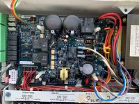
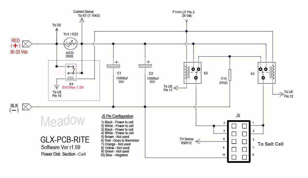
I went through some of the troubleshooting steps I found online and found a bad 20A fuse on the board. I replaced the fuse and left the cell disconnected. After powering back up as soon as the relays switched on it blows the same fuse. For complete disclosure I did fix a cold solder joint on a relay about 5 years ago for a similar error message. It was not blowing any fuses at that time and it has run trouble free since that repair.

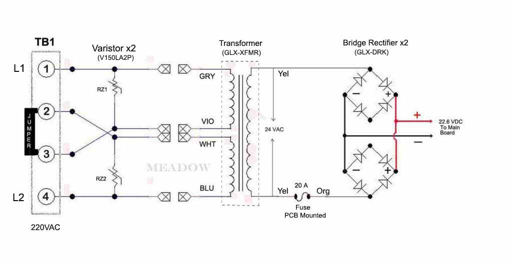
I plan to replace the cell anyway but think there is clearly another problem that I need to resolve first. I confirmed 24V AC on the yellow wires. The resistance on the white/black and violet/grey wires is within the specs I found.

Do I need to replace the board or is there something else I should check like the rectifiers. I am comfortable doing some electronic repairs if possible.

Any help much appreciated. I can supply PICS or any additionl info if needed. Thanks in advance!

mb
 
Last edited:
There is probably a short on the board somewhere. Inspect the board for any debris that may have caused a short. Otherwise, it could be one of the relays that is not switching when it should (bad driver).
 
I looked over the component side of the board and see no obvious burns or debris shorting anything. I still need to look at the underside.
Here's a PIC. The 20A fuse is out. The unit seems to work normally except for the chlorinator circuit. I have more close ups if needed. Thanks.
 

Attachments

  • IMG_2243.jpg
    IMG_2243.jpg
    401.9 KB · Views: 30
The two yellow wires are the 24 volts AC from the transformer.

The voltage goes to the orange wires through the circuit board.

One leg (yellow to orange) goes through the 20 amp fuse.

The two orange wires go to the rectifiers.

The output of the rectifiers are the red and black wires which are about 25 volts DC.

Disconnect the red and black wires from the circuit board with the power off and test the resistance between the two terminals where the red and black wires connect.

GLB-PCB-RITE_Low_Voltage_Power_Supply.jpg
 
It would seem that something downstream from the orange wires is shorting out.

Maybe the rectifiers or something on the board downstream from the red and black wires coming from the rectifiers.

GLX-PCB-RITE_Pwr_Dist_Salt-Cell_r159.jpg
 

Enjoying this content?

Support TFP with a donation.

Give Support
Disconnect the red and black wires from the circuit board with the power off and test the resistance between the two terminals where the red and black wires connect.

Can you show the rest of the pictures?

Can you show the back of the board and the rectifiers?

Test the resistance from one orange wire to the other orange wire.
 
The two yellow wires are the 24 volts AC from the transformer.

The voltage goes to the orange wires through the circuit board.

One leg (yellow to orange) goes through the 20 amp fuse.

The two orange wires go to the rectifiers.

The output of the rectifiers are the red and black wires which are about 25 volts DC.

Disconnect the red and black wires from the circuit board with the power off and test the resistance between the two terminals where the red and black wires connect.

GLB-PCB-RITE_Low_Voltage_Power_Supply.jpg
The resistance between the red and black terminals is ~ 4Kohms.
 
You can also try powering up with the red and black wires disconnected to see if the fuse still blows.
Powered up with black and red disconnected. Starts up with fuse intact. I measured the voltage on the red and black wires while powered up and am seeing only 2 volts !
 
Can you show the rest of the pictures?

Can you show the back of the board and the rectifiers?
Here ya go. Nothing exciting. The solder joint on the relay I repaired years ago could look better. I might clean it up again while I'm here....
 

Attachments

  • IMG_2246.jpg
    IMG_2246.jpg
    537.8 KB · Views: 21
  • IMG_2247.jpg
    IMG_2247.jpg
    266.3 KB · Views: 21
Last edited:
With the power off, swap the Orange leads on each rectifier to the open lug (diagonal) and see if the voltage changes. Do not change the Red or Black leads. You may have a bad rectifier but there is a spare set of diodes in each rectifier that may still be good. Also, it is possible the rectifiers are causing the short.
 
With the power off, swap the Orange leads on each rectifier to the open lug (diagonal) and see if the voltage changes. Do not change the Red or Black leads. You may have a bad rectifier but there is a spare set of diodes in each rectifier that may still be good. Also, it is possible the rectifiers are causing the short.
Orange leads swapped to uused posts on the rectifiers. Now reading 6 VDC on the red and black leads.
 
That is still too low. What is the AC voltage across the two orange wires?

Looks like you might have bad rectifiers.
 
That is still too low. What is the AC voltage across the two orange wires?

Looks like you might have bad rectifiers.
That's the feeling I'm getting. I am basically getting no AC voltage (0.7 V) on the orange leads. 23.8 VAC on the yellow leads from the tansformer.
 

Enjoying this content?

Support TFP with a donation.

Give Support
Thread Status
Hello , This thread has been inactive for over 60 days. New postings here are unlikely to be seen or responded to by other members. For better visibility, consider Starting A New Thread.