
Recent content by rajthepilot
-
R
System Manual Off
Hi All, I saw the message (System Manual Off) for the first time on my Aqua Logic Display. I'm not sure what caused that to come up on the display, but I was then unable to turn the pump on. I had to reset the configurations and then I was able to turn the pump on. But then I didn't realize...- rajthepilot
- Thread
- Replies: 1
- Forum: Everything Else
-
R
AC Wire Removal
the board has a 8 wire plug, 2 for each of the relays, so I won't be able to pull it off there. That's why I wanted to secure the hot wires from touching the relays- rajthepilot
- Post #4
- Forum: Everything Else
-
R
AC Wire Removal
While testing the AC voltage at the relays that are powered by the Aqua Logic Circuit Board, I inadvertently touched the leads and caused a short circuit on my 4th relay (1st relay is for pump, 2nd is for lights, 3rd and 4th aren't connected to anything). The 4th relay now constantly receives...- rajthepilot
- Thread
- Replies: 4
- Forum: Everything Else
-
R
Aqua Logic Transformer
Thank you for the explanation. It'll take a bit of time to sink in.- rajthepilot
- Post #7
- Forum: Pool Automation
-
R
Only one display works
I am. I was not able to figure it out- rajthepilot
- Post #3
- Forum: Everything Else
-
R
Aqua Logic Transformer
I've bene spending time learning the technical side of the pool equipment. I had a question about the transformer and the two rectifiers. Based on the pictures below, the transformer has two output wires (K - Both Yellow) (to get 24 VAC), but 4 input wires of 120 VAC (H - Gray, Violet, White and...- rajthepilot
- Thread
- Replies: 16
- Forum: Pool Automation
-
R
Only one display works
I have 2 Aqua Logic Displays with my pool system. One is outside next to filter, chlorinator and heater. The other is inside the house (same as outside except it doesn't have a service button). They are both connected to GLX-PCB-MAIN Circuit Board. Few days ago, the buttons on the outside...- rajthepilot
- Thread
- Replies: 3
- Forum: Everything Else
-
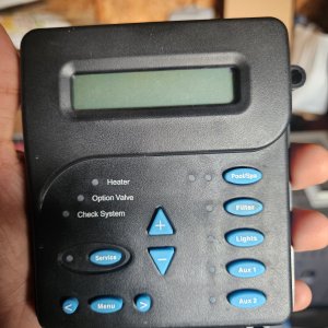
Aqua Logic Display - Display that connects directly to Circuit Board.jpg
- rajthepilot
- Media item
- Comments: 0
- Category: Pool Equipment
-
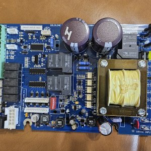
New Circuit Board GLX-PCB-MAIN received on May 24 2023 (1).jpg
- rajthepilot
- Media item
- Comments: 0
- Category: Pool Equipment
-
R
AUX2 relay is always getting power
Based on the pictures below, the transformer has two output wires (K - Both Yellow) (to get 24 VAC), but 4 input wires of 120 VAC (H - Gray, Violet, White and Blue). Why does the transformer need 4 inputs of 120 VAC?- rajthepilot
- Post #20
- Forum: Everything Else
-

Rectifier and Transformer Wiring Instructions.jpg
- rajthepilot
- Media item
- Comments: 0
- Category: Pool Equipment
-

ProLogic Main PCB Layout.jpg
- rajthepilot
- Media item
- Comments: 0
- Category: Pool Equipment
-
R
AUX2 relay is always getting power
Based on the pictures below. Two Orange Wires (J) with 24 VAC are going to the rectifiers, one to each rectifier. Red and black are coming back from the rectifiers with 18-33 VDC and red and black are connected to each other. Can anyone explain how this circuit works. I understand that...- rajthepilot
- Post #19
- Forum: Everything Else
-

ProLogic Main PCB Layout.jpg
- rajthepilot
- Media item
- Comments: 0
- Category: Pool Equipment