Jandy aquapure 120 error

mc2021

Gold Supporter
Silver Supporter
Jun 9, 2020
157
Chicago
Pool Size
40000
Surface
Plaster
Chlorine
Salt Water Generator
SWG Type
Jandy Aquapure 1400
Hi,

I'm getting a 120 error on my aquapure. I'll have to do the diagnostics later but I was wondering if it's OK to keep it running until then. It's still creating chlorine but I can turn it off if I'm risking further damage.

Thanks
 
Ok, im going to pick up a clamp meter today and will test it. Is there a way to force it to reverse polarity?
 
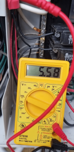
I turned the percentage to zero this morning and when I turned it back on to test the error was gone. I did test it though. In reversing it was 3.8 and normal was 3.2. This seems low based on what I see others posting. I guess I'll have to keep an eye on it and test again if the error returns?
 

Attachments

  • 20240916_171134.jpg
    20240916_171134.jpg
    380.7 KB · Views: 9
I just looked through the manual and specs and this one doesn't do DC amps. I'll take it back and get the right one tmrw. I have this one coming, looks ok?
 
  • Like
Reactions: JamesW
You can access the cord wires where they connect. You can measure DC amps using an inline or clamp method.


71EIKfDwbXL._AC_SL1500_.jpg


You can access the wires by clamping around the blue or red wire or using an inline test in the red or blue wire.

For an inline test, just disconnect the red or blue wire and put the meter in series so that the current goes through the meter.

You're going to be measuring current. We're assuming that the voltage is probably ok.

The voltage should be between 24 to 30 volts dc and the current should be between 5 and 8 amps dc.

Maybe show a picture of your test setup to verify before you power the cell to make sure that it's correct.

Do you want to do a clamp on test or an inline test?

What meter do you have?

That will work. You will disconnect the red wire female connector from the male connector and put one lead in the female terminal and the other lead will connect to the male terminal. That way, the current will flow through the meter.

Note: Do not test voltage with the meter set like that or it will create a direct short and damage the meter.

1726537693068.png
 
If you use the inline method, make sure that you get the leads in the right terminals or you can blow up the meter.

After doing an inline current test, make sure that you change the leads back to the voltage terminals before testing voltage or you will blow up the meter.
 

Enjoying this content?

Support TFP with a donation.

Give Support
Thanks James, I'll probably just wait for the clamp meter since it should be here early tmrw. This is the 3rd time I've needed one the last few years so it's time to just get one.
 
  • Like
Reactions: JamesW
New clamp meter just showed up. 4.3 on the blue and -4.1 on the red. I'm waiting for it to reverse in a bit.
It seems like when I put the cell ar 100% the error goes away so I was able to test with no error and the amps were the same. Not sure if that means anything though. Will post back once it reverses unless you know of a way to force that.20240917_095031.jpg
 
4.1 is low.

A good cell is about 5.6 amps.

It is probably on the border of where it gives an error.

Typically, the center pin is the fault point.

You can remove the screws on the pressure plate at the pins and remove the plate to check the pin.

You can switch the cell type to 700 by cutting the jumper.

That might give you some more life.

You would have to reconnect the jumper later if you go back to a 1400 cell.

1726585815846.png

  • PURE700 - 0.625 lb./24 Hr. (283 gm/24 Hr.)
  • PURE1400 - 1.25 lb./24 Hr. (567 gm/24 Hr.)


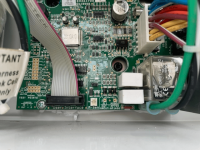
Both cells use the same Power Center box. However there is a jumper on the Power Interface Board that is connected for the 1400 cell and cut for the 700 cell. The Power Center comes configured for the 1400 cell and the JL1 jumper must be cut if using the 700 cell.

1726585877830.png

1726585903379.png


If you are switching from the 700 cell to the 1400 cell the JL1 jumper needs to be reconnected.

The PLC700's have a 2 prong plug system and the PLC1400's have a 3 prong plug system.

Page 17 in the Jandy Power Center Installation Manual shows the location of the jumper.

The center prong is the most common point of failure. You can usually see evidence of a leak when you know to look for it.

1726585948817.png


1726586007983.png

1726586020532.png
 
What is the actual salinity (as measured by a K-1766 salt test kit)?

What is the box showing for salinity?

You can also test the cell voltage while the cell is producing by measuring DC Volts at the connections.

Insert the voltage probes into the red and blue wire 1/4" spade terminals or create a short jumper for better access.

1726586543981.png
 
Salt with 1766 is 3000 and system reads 3100.

Cycling power does in fact reverse polarity. I also looked at the pins while off and everything looks fine. Now I'm getting -5.8 on the blue and 5.25 on the red and no error message while reversing.

Should I power cycle again and see if the amps are higher in normal mode now? Maybe there was some dirt on the pins?
 

Attachments

  • 20240917_102551.jpg
    20240917_102551.jpg
    238.7 KB · Views: 3
  • 20240917_102531.jpg
    20240917_102531.jpg
    250.5 KB · Views: 3
  • 20240917_102520.jpg
    20240917_102520.jpg
    290.4 KB · Views: 3
Installed in Sept 21, with our short season probably has 15 months of runtime.

In normal mode it's showing 4.5 and -4.5 now. As I'm typing this the service light went on and the amps are now 4.3 and -4.5. Seems like 4.5 is close to the line?
 

Enjoying this content?

Support TFP with a donation.

Give Support