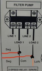
After almost a year of procrastination, I finally have an RJ60+ in hand and I'm ready to install it. I am unsure of the wiring because I have a two-speed pump hooked up to a Polaris EOS control center that was installed by the prior homeowners. I have attached some photos and diagrams below.
The wiring diagram for the EOS appears to show the pump connected to High Power Relay 1 and Optional two speed Pump Relay at location 5 directly below. The pump is wired as follows (labeled in the photographs):
1: Red wire/switches to yellow at the wire nut: attached to the two-speed relay
2: Blue wire: attached to the two-speed relay
3: Black wire: attached to the high power relay (looks like the "load" position according to diagram)
4: Green wire: runs to the ground section on the right
There is also a short red wire (unlabeled) running between the two-speed relay and the high-power relay, attached to the rightmost screw on the high-power relay (appears to be "load" based on diagram).
My best guess is that I attach the black and white wires from the RJ60+ to High-Power Relay 1, to the same terminals that the black wire (3) and the unlabeled red wire are attached to. Then the green wire obviously goes off to the ground section. Assuming that is correct, this still leaves a few questions:
-The terminals are going to be crowded because they already have two wires and will get a third. In terms of making a safe connection, should I twist the ends of the wires together or keep them separated as much as possible?
-Does it matter which of the two load terminals the black and white wires go to, or are they interchangeable?
-Would I have any reason to switch the jumper on the RJ60+ from 240 (listed as default in manual) to 120, and how would I know if that is needed?
-The way I am thinking this needs to be wired, the two-speed relay basically just gets ignored. If I do it this way, will the SWG turn off and on correctly at the same times as the pump, regardless of the speed?
Thanks in advance for help with this.


