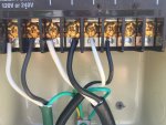
I have incoming power wired in as white wire to lug 1, black wire to lug 2, green wire to ground lug in timer box. Timer works and I have set the time and set up events for circuit 1 and 2. Timer is set to 120 volts and is in Mode 1.
Circuit 1 is my circulation pump. I cut the plug off and attached the white wire to lug3, and the black wire to lug4, and the green wire to the ground lug.
Circuit 2 is my Stenner pump. I cut the plug off and attached the white wire to lug 5, the black wire to lug 6, and the green wire to the ground lug.
Since I don't understand what the manual means by line and load, this is what I though they meant. However, circuits 1 and 2 do not work. Pressing the on/off button will cause a slight click, and the indicator will show aux1 or aux2. But the pump2 do not come on!
I hope the attached photo will make sense to you if my description doesn't.
Where have I gone wrong?