
Vacuum release not closing
- Thread starter Sticky
- Start date
You are using an out of date browser. It may not display this or other websites correctly.
You should upgrade or use an alternative browser.
You should upgrade or use an alternative browser.
Jumping in here. I thought solar sensor was meant to be exposed to the same sunlight and NOT in contact with the actual panels. Reason being if the panels are cooled by the water movement, the sensor in contact would read lower temps and not the heat that is available from the sun.
You maybe right cause when I touch the panels they are cool , it does say if the panels are glazed to put the sensor inside the glazing but with these panels there is no room .
Sorry internet has been out here for the last 8 hours or so, Jason it appears that there is some variation in the instructions online on placement of the sensors depending on brand of controller / solar panel, however all the controller work about the same, the sensor is to measure available heat at the panel, most solar controllers with activate at a about 3 degree F or about 1.5 degree C temperature increase at the panel over the pool water. And turn off when temperature at panel gets within about 1 degree F or .5 degree C of matching the pool temperature.
Upon thought my guess is this is a matter of weighting of different factors, mounting so it is not touching the panel has the advantage of not doing rapid cycling of the controls in case of very high water flow through the panels since most solar panel installation guides include sections saying flow should be set by flow meter or by set temperature rise of about 1-2 degrees F some even say up to 5 degree F.
Where those suggesting mounting in contact with panels are more concerned about not loosing heat to potential wind and radiation cooling, etc.
I suspect either way will work, at least much better than having no solar controller, but I feel a sensor in contact with the panel would provide best overall performance, at least in a well designed system with proper flow rates, and with the sensor installed near the output side of the panels.
Picture if you will a location like Jason has in AZ likely with low humidity and where temperature can rapidly drop at sunset In a case like this I can see a situation in the afternoon where a separately mounted solar sensor would still be showing available heat even though no positive heat input would be available at the panels due to a combination of convection and radiation.
I can say that my sensor is mounted in direct contact with my panel, and I have experienced no problems with short cycling of the controller with a flow rate of around 3.3 gpm per 4x12 panel (35 gpm measured by flow meter through 11 panels), which is a little less than stated optimum, but is limited by my pump operating on high speed.
Ike
p.s. looks like my internet problems continue, I had to wait for it to come back on again in order to post that message, so if disappear assume my net it out
The sensor seems to be working ok where it is , if I where to attach it to the panels it read the temp of the panels but where solar is running the panels are cool to touch . So the sensor would them be reading the cool panels not the available heat . does that sound right ? .
I would say we have solved why the VRV is not closing , to many outlets on the return side creating a siphon/suction effect on the VRV .
Now I have to work out how to get the SunTouch to operate to valves in Solar mode , so i can direct all the flow to the deep return .
I will make a new post on this .
Ike and Jason thank for your help on this greatly appreciated .
Dave
- May 3, 2007
- 17,069
- Pool Size
- 20000
- Surface
- Plaster
- Chlorine
- Salt Water Generator
- SWG Type
- Hayward Aqua Rite (T-15)
I would say it is an improper VRV location given your plumbing setup. Having multiple outlets does reduce the pressure at the VRV but that just means you need to make other adjustments. Either increase the pump speed to raise the pressure at the VRV or move the VRV closer to the pump at a lower height to increase the pressure at the VRV. Remember that a rise in height is a loss in pressure due to static head loss.Sticky said:I would say we have solved why the VRV is not closing , to many outlets on the return side creating a siphon/suction effect on the VRV .
Hi Mark
Increasing pump speed is what I am trying to avoid as it increases energy usage plus excess pressure in the panel according to hot2suns website. With all outlets open I have to run at least 40gpm to keep it closed with just the deep return 30gpm this uses 150watts less and is closer to the rated 4gpm per panel, 3 panels x 4 = 12gpm .
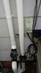
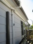
If I was to move the VRV lower could it go on the solar return on the house wall above the nonretyurn valve ? , the pipe on the right say near the eves.
Increasing pump speed is what I am trying to avoid as it increases energy usage plus excess pressure in the panel according to hot2suns website. With all outlets open I have to run at least 40gpm to keep it closed with just the deep return 30gpm this uses 150watts less and is closer to the rated 4gpm per panel, 3 panels x 4 = 12gpm .
If I was to move the VRV lower could it go on the solar return on the house wall above the nonretyurn valve ? , the pipe on the right say near the eves.
Attachments
- May 3, 2007
- 17,069
- Pool Size
- 20000
- Surface
- Plaster
- Chlorine
- Salt Water Generator
- SWG Type
- Hayward Aqua Rite (T-15)
Actually you want the VRV on the solar supply side (i.e. closer to the pump) because the pressure is higher on that side so it is easier to keep the VRV closed. Also, you want the panels to drain down through the return side pipe. You can put the VRV a few feet above the filter and that should be enough to keep it closed at low GPM/RPM.
However, you will still need to set up the pump so that it will prime the panels above 40 GPM and then step down after priming. This is the critical flow rate which is required to push air downwards out of the return pipe when priming the panels. Slower flow rates will probably not fully prime the panels.
Also, during priming the pressure needs to be high enough to lift the water to the height of the panels so if they are 15 feet high, the filter pressure needs to be at least 7 PSI+ to lift the water that high.
I did Have a VRV supply side about 2 feet above the top of the pic , but the installer blocked that off and drilled a hole in the return side non return valve that you can see .
If I put that back and took the one off the roof would the panels still drain ok the way the plumbing is configured ? .
If I put that back and took the one off the roof would the panels still drain ok the way the plumbing is configured ? .
- May 3, 2007
- 17,069
- Pool Size
- 20000
- Surface
- Plaster
- Chlorine
- Salt Water Generator
- SWG Type
- Hayward Aqua Rite (T-15)
Yes, the panels still should drain well. In some parts of this country, placement of the VRV in this location is fairly common practice. Also, it is a much better location for draining than the return side because it will drain faster.
However, in the other post you mentioned two valves. I would avoid the second valve on the return side. You want the panels to drain quickly so no water is trapped in the panels. With an actuated valve, there is a possibility that water could get trapped in the return side and should this happen during the day in the hot sun, it can soften the PVC pipe.
A better alternative to get water to go to the deeper returns is to put smaller eyeballs on the top returns and larger eyeballs on the bottom return. You need to compensate for the depth difference between the returns. This will put a little more velocity on the surface returns where it can do some good with skimming plus force a bit more flow rate to the deep returns. Also, efficiency wise it is much better too because you converting the extra head loss into useful work while using a valve is just extra head loss.
Also, one more thing I wanted to point out is that your original plan to restrict the return side in order to close the VRV would be less efficient than simply increasing the speed of the pump. You are basically forcing the same head loss in both cases but with different flow rates.
mas985 said:Yes, the panels still should drain well. In some parts of this country, placement of the VRV in this location is fairly common practice. Also, it is a much better location for draining than the return side because it will drain faster.
So it would be drain back through the supply side would I need to drill a hole in the non return valve and the 3 way solar valve as it is set up now it drain thru the return there is a hole in the non return valve . You can see where the blocked off VRV was on the solar supply line in the pic . Below that is a non return and then the solar vale .
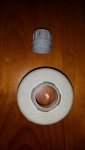
The returns are 40mm . I replaced all the 40mm (1 1/2in ) pipe with 2inch up to where it goes into the pool . I had a goolge and it is hard to find 40 mm eyeballs with smaller holes here in Australia . I could try fitting some garden hose inside the existing eyeball and removing the bottom return .
Mark I see the reasoning behind this and I will give it a try but will it not affect the efficiency of the normal filter cycle of the VF pump ? . The idea of replace all the restrictive 1 1/2 in piping was to allow the VF to run as freely as possible . The VF runs at 30gpm using 120watts maybe with smaller eyeball I could running filter at 25gpm ? I am going out to see if I can MacGyver the eyeballs smaller . :idea:
The more restrictive returns will introduce a permanent restriction into the system . I thought blocking or partially blocking off the shallow returns temporarily while solar is running would be a more adaptable system .
Attachments
- May 3, 2007
- 17,069
- Pool Size
- 20000
- Surface
- Plaster
- Chlorine
- Salt Water Generator
- SWG Type
- Hayward Aqua Rite (T-15)
Water drains away in both directions away from the VRV. So with a VRV on the supply side, MOST of the water drains up and then down the return side. Only the water that is below the VRV needs to drain down the supply side. But yes a small hole can be drilled in the valve face to allow for draining when the valve is shut off. A solar valve has a small check valve built into the valve so this hole is not required.
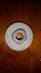
By eyeballs, I was not referring to the feed pipe but to the exit orifice in the pool. Eyeballs look like this:
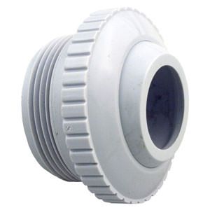
In the US, they come in 1/2", 3/4" and 1"
The feed pipe should remain large to increase efficiency.
But all that is moot if you use the lower supply side VRV as that should fix the problem and allow you to run on lowest RPM possible without having to restrict the return side. Although, you may never get down to the 12 GPM specification because no matter what, I doubt that will produce enough pressure to keep the VRV closed even at the lower elevation. But it should be much better than what it is now.
By eyeballs, I was not referring to the feed pipe but to the exit orifice in the pool. Eyeballs look like this:
In the US, they come in 1/2", 3/4" and 1"
The feed pipe should remain large to increase efficiency.
True but that is a much much less efficient way doing things. At least with the eyeball reduction, you are trading off exit velocity for the extra head loss. With the valve, you get nothing back.The more restrictive returns will introduce a permanent restriction into the system . I thought blocking or partially blocking off the shallow returns temporarily while solar is running would be a more adaptable system .
But all that is moot if you use the lower supply side VRV as that should fix the problem and allow you to run on lowest RPM possible without having to restrict the return side. Although, you may never get down to the 12 GPM specification because no matter what, I doubt that will produce enough pressure to keep the VRV closed even at the lower elevation. But it should be much better than what it is now.
Eyeballs yes those are what I have been eyeballing but but I can not find the for sale in Australia . you would not believe the limited range of everything here before the net we didn't know but .
I will try moving the VRV and see if it closes and drians ok . but I will still have the issue of the bottom return , I will hunt around the pool shops for smaller eyeballs .
Thanks for your patience Mark .
I will try moving the VRV and see if it closes and drians ok . but I will still have the issue of the bottom return , I will hunt around the pool shops for smaller eyeballs .
Thanks for your patience Mark .
Hey well tried my reduced eyeballs and it did help send more water to the deep return . But have having the VRV on the wall caused it to when draining sort of shudder I think becuase its not drianing thru the supply side the VRV stays closed till the vucuum effect is enough to drag some air up them water fall back down and closes it again .
Teh water coming down has no where to go becuase of the non return valve and the solar valve is shut so the pressure of the water up to the eves is holding it shut .
The only other place is where the supply goes it to the panels ?? I have seen this mentioned on another VRV post .
Teh water coming down has no where to go becuase of the non return valve and the solar valve is shut so the pressure of the water up to the eves is holding it shut .
The only other place is where the supply goes it to the panels ?? I have seen this mentioned on another VRV post .
- May 3, 2007
- 17,069
- Pool Size
- 20000
- Surface
- Plaster
- Chlorine
- Salt Water Generator
- SWG Type
- Hayward Aqua Rite (T-15)
One thing to keep in mind is that the panels will not drain while the pump is still on. The pressure from the pump will hold the water in the pipes and maybe the panels too. They will only fully drain when the pump is shut off so is this happening when the pump shuts off and the valve closes?
Most of the water should drain through the return side and not the supply side but some will fall back down on the supply side depending on how quick the valve closes. Have you drilled a hole in the supply side valve yet? That may be necessary to full drain the supply side.
Most of the water should drain through the return side and not the supply side but some will fall back down on the supply side depending on how quick the valve closes. Have you drilled a hole in the supply side valve yet? That may be necessary to full drain the supply side.
I don't understand this question.The only other place is where the supply goes it to the panels ?? I have seen this mentioned on another VRV post .
Hi just an update,
Well finally got round to installing the second valve actuator and relay on the two shallow returns and moved the VRV down where it use to be nearer the filter .
The system runs at 27gpm with no air getting in , i am lowering it 1gpm to see how low I can get . At 27gpm there is still a quite strong flow from the return . The water didn't feel as warm as I thought it should this I wonder is becuase optimum flow for each panel is suggested at 4-5gpm X 3 = 12 -15gpm , I dont think I will get that lower but the lower the better right ? .
Dave
Solar heating is most efficient at higher flow rates where the water is only heated a few degrees. The lower the flow rate, the lower amount of heat added to the pool even though the delta temperature across the panels may be higher.
Sounds like you may want to divert some of the water around the solar and not through it.
Sounds like you may want to divert some of the water around the solar and not through it.
http://www.troublefreepool.com/threads/9248-Solar-Panel-Technology-Comparisons chem Geek suggests here a flow of 4-5 gpm per panel generally . my panels hold 3.32gal including header per panel , So I should be aiming for 15gpm for the whole system ? .
It all comes down to the VRV staying close at such low flow and the return water not creating a vacuum/siphon effect and trying to collapse the pipes .
The other option to run the pump at 30gpm at use the divert valve to lower the flow ,thou this uses more electricity . Should I just accept this it might be easier . ??
Thread Status
Hello , This thread has been inactive for over 60 days. New postings here are unlikely to be seen or responded to by other members. For better visibility, consider Starting A New Thread.