Howdy y’all. I am also tripping the 3amp relay on my pentair easytouch (my salt cell chlorinator IC20 is also out) so I’m hoping that replacing the relay driver chip will be the fix. However, I’m having trouble identifying where they are located. Are they on the side of the motherboard that is accessible when you fold down the control screen? Or do I need to remove the screws from the motherboard and access them on the opposite side? Appreciate any guidance!

Troubleshoot tripping breaker on Pentair EasyTouch
- Thread starter as1430txstate
- Start date
You are using an out of date browser. It may not display this or other websites correctly.
You should upgrade or use an alternative browser.
You should upgrade or use an alternative browser.
As,
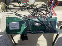
They are in sockets on the LCD side of the main card. Note how they are installed before taking them out!!!
Thanks,
Jim R.
They are in sockets on the LCD side of the main card. Note how they are installed before taking them out!!!
Thanks,
Jim R.
Hi Jim. The new chips worked like a charm and the 3amp relay no longer trips and the lights on the salt chlorinator ic20 light up. BUT, the variable speed pump will not turn on using the easy touch. When I go to settings for the inteliflo pump on the control panel is says NO COMM. Any ideas?As,
They are in sockets on the LCD side of the main card. Note how they are installed before taking them out!!!
Thanks,
Jim R.
Thanks in advance for any suggestions!
As,
It could be you took a lightning hit and it took out the relay drivers as well as your com port.
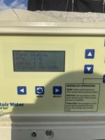
Step 1 in troubleshooting a com port failure on an EasyTouch is to connect just the pump (And nothing else) to the J20 com port. Then go look at the pump and see if the display shows "Display not active". It should. System must be in Auto... Can take a minute or so to switch..
Let us know what you find.
Thanks,
Jim R.
It could be you took a lightning hit and it took out the relay drivers as well as your com port.
Step 1 in troubleshooting a com port failure on an EasyTouch is to connect just the pump (And nothing else) to the J20 com port. Then go look at the pump and see if the display shows "Display not active". It should. System must be in Auto... Can take a minute or so to switch..
Let us know what you find.
Thanks,
Jim R.
Hi Jim,
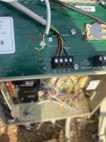
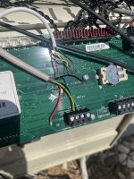
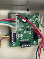
I believe I followed your instructions correctly- the only other thing attached to the J20 comm port was the wireless controller, so I took those wires out (see attached pics). Nonetheless, the display on the easy touch system at settings > pump > inteliflo still displays “no comm.” The LCD on the physical inteliflo pump does NOT show “Display not active.” Am I looking in the wrong spot?
I believe I followed your instructions correctly- the only other thing attached to the J20 comm port was the wireless controller, so I took those wires out (see attached pics). Nonetheless, the display on the easy touch system at settings > pump > inteliflo still displays “no comm.” The LCD on the physical inteliflo pump does NOT show “Display not active.” Am I looking in the wrong spot?
Attachments
A,
The problem that I see is that the cable from the pump only has two wires,, Yellow and Green
I suspect that the line in your pic that is connected to J20 is a jumper that goes the the surge card for a SWCG. The surge card also has RS-485 chips.
You need to connect just the pump and nothing else to J20.
Thanks,
Jim R.
Which pump do you have? Intelliflow communication cable is black with a yellow and green conductor.Hi Jim. The new chips worked like a charm and the 3amp relay no longer trips and the lights on the salt chlorinator ic20 light up. BUT, the variable speed pump will not turn on using the easy touch. When I go to settings for the inteliflo pump on the control panel is says NO COMM. Any ideas?
Thanks in advance for any suggestions!
A,
I kind-of lost where we were...
If the pump and the EasyTouch can talk with one another, that should mean that the pump and main card are working and something else on the com bus is bad
But I am confused.. Your pic shows a cable with 4 wires going to J20. Two of the wires are not connected.. but.. That is not the normal cable that goes to an IntelliFlo pump. Is that just an old pic? Where does that cable go??
Thanks,
Jim R.
The 4 wires that are completely detached go to the wireless control transmitter. The green and yellow wires I left attached as per your directions. Those two wires and the red and black that are detached go to the easytouch load center SCQ surge board (see attached photo)A,
I kind-of lost where we were...
If the pump and the EasyTouch can talk with one another, that should mean that the pump and main card are working and something else on the com bus is bad
But I am confused.. Your pic shows a cable with 4 wires going to J20. Two of the wires are not connected.. but.. That is not the normal cable that goes to an IntelliFlo pump. Is that just an old pic? Where does that cable go??
Thanks,
Jim R.
Attachments
A,
So J20 is currently connected to the surge card and to the pump. The un-connected Red and Black wired are what powers the surge card's RS-485 com port and the cell's Com port.
Disconnect the big white connector on the surge card. The one that goes to the cell.
Then re-connect the Red and Black wires to J20 along with the yellow and green that are already there.
Fire things back up and see if the pump still says "Display not active"... If it does, then re-connect the large white cable to the surge card and see if the pump still shows "Display not active". If it does, great.. If not, then the cell is most likely bad or maybe the surge card.
Thanks,
Jim R.
Hey Jim,
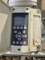
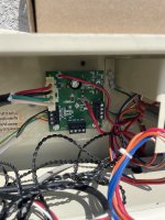
Followed your instructions and I’m still getting “Display not active.” Funny thing is, before I even posted on the forum, was that I replaced the surge card with a new one in attempt to get my salt chlorinator working (recall the lights were out on the salt chlorinator and the 3amp relay was tripped). This did NOT provide a fix. So I put the old surge card back in and installed the new relay chip as you suggested. That action got power back to the Salt chlorinator (lights are back on), but resulted in the Inteliflo pump not communicating with the easy touch system. The “old” surge card has its green led light on, so I presume it’s good (see photo)?
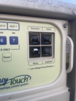
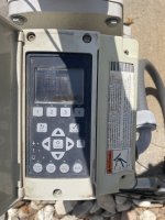
I can get the pump to turn on if I active the pool cleaner booster pump (which is next one down the panel buttons, J9 or J10, I believe). Maybe these got switched around when I took everything off to replace the chip?
Followed your instructions and I’m still getting “Display not active.” Funny thing is, before I even posted on the forum, was that I replaced the surge card with a new one in attempt to get my salt chlorinator working (recall the lights were out on the salt chlorinator and the 3amp relay was tripped). This did NOT provide a fix. So I put the old surge card back in and installed the new relay chip as you suggested. That action got power back to the Salt chlorinator (lights are back on), but resulted in the Inteliflo pump not communicating with the easy touch system. The “old” surge card has its green led light on, so I presume it’s good (see photo)?
I can get the pump to turn on if I active the pool cleaner booster pump (which is next one down the panel buttons, J9 or J10, I believe). Maybe these got switched around when I took everything off to replace the chip?
Attachments
A,
On the main card, follow the wires from the relay connectors and make sure they run to the correct relays..
J8 should go to the Pump/Filter relay, J9 to Aux 1, J10 to Aux 2... etc.
The surge card has two functions..
1. To generate the DC voltage needed to run the salt cell
2. To deliver the RS-485 signals to the SWCG. This also give you two more places to connect Com Port cables.
With the 3 amp breaker popped, the surge card can not generate the DC voltage, because the pump filter relay can not close.. I suspect the original card is good.
The second surge card is either bad for RS-485 issues, or you have something mis-wired.
I suggest that you connect everything back up except the wireless cable and see what happens. Push the Reset button on the main panel and see if everything starts back up. I am assuming that you still have a normal schedule that should tell the pump to run, etc.. Keep in mind that it can take a few minutes for everything to restart after pushing the reset button. Make sure you are not in the Service mode when you push the reset button.. It is just like rebooting your PC and it will not erase anything.
Pushing the "F" button will not always make the pump start as it depends on other things..
Once you know it all works, re-connect the wireless cable and see if that stops your com port.. If not, then you should be good to go.
Thanks,
Jim R.
Thanks,
Jim R.
Thread Status
Hello , This thread has been inactive for over 60 days. New postings here are unlikely to be seen or responded to by other members. For better visibility, consider Starting A New Thread.