TriStar and aqualink rs8 compatible

Ororen

In The Industry
May 21, 2023
6
Hamilton
I purchased

Hayward W3SP3206VSP TriStar VS Variable-Speed Pool Pump, 2.7 HP

And I’m trying to connect it to the

Jandy Aqualink RS8

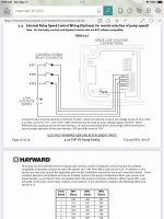
I understand that they are not compatible with the low voltage wiring. So I followed the instructions for the relay installation method. I dedicated 4 relays - 1) is the 220 input to turn the pump on and off. 3) is to control the variable speed. I used the COM as a power supply as instructed in the Hayward manual. I know my jandy relays are operating correctly. I tested my relays and they are working correctly. And I set the pump on external relay control on the Hayward interface.

After the pump is priming the relay still does change the speed of the pump.

I have spent several hrs with haywArd technical support and I’m yet to find a knowledgeable person. Please help!
 
After the pump is priming the relay still does change the speed of the pump.

Post pics of your wiring.

You have Dipswitch #1 ON?

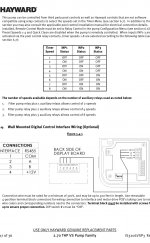
You have different speeds set in Timer Speed 2 & 3?

You check with a multimeter you have voltage?

IMG_0996.png
 
I do have dipswitch 1 on.
I put it on the service and manually started my relays. They close the circuit. And on the pump side I have between 12-30 volts on each input.
But the pump doesn’t work. Thanks for your reply- fingers crossed we don’t need to replace the pump.
 
Post pics of your wiring in the Aqualink and Tristar.
 
I don’t know if I have different speeds in timer two and three. I thought once you put it on a relay the interface doesn’t do anything but turn it on and off.
The interface tells the pump to run one of the speeds set in the pump.

You need to set the speeds you want in the pump speeds 1, 2, 3, & 4.
 
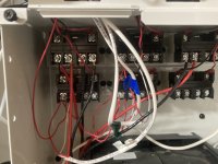
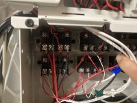
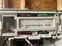
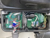
The pictures show I didn’t have a CAT6 wire for the low voltage so I used three different 22 gauge wires. I ran it to the high voltage relays however I only fed it with the 12 voltCOM from the pump. The only relay that is receiving 220 is the first relay to feed the pump power.

I was thinking about the presettings, so I went ahead and reset the pump to factory settings. And only changed the pump from stand alone to remote relay. That still didn’t solve the problem.

What do you think?
2AAF5992-B875-4561-BB4D-262C26568B5F.jpeg8343EB6E-B8BC-426E-ACBE-B8707142194B.jpegA4374EF8-CB61-46EB-9701-669446D9970B.jpegA17A3BC9-8BD3-4DC8-86B8-477DCA297265.jpeg
 
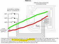
You have to connect to both the 12V and COM terminals to pickup the 12 volts.

That red wire you ran from COM to the second INP1 connection is correct but the other red wire to that connection should go to the 12V screw (or maybe the reverse depending on polarity).

I do not know if polarity matter and if the 12V is + or -. I would use a multimeter to measure the DC voltage and connect the + and - as shown on the diagram. So the red and green wires I drew may need to be reversed.

1684689431871.png
 
You have to connect to both the 12V and COM terminals to pickup the 12 volts.

That red wire you ran from COM to the second INP1 connection is correct but the other red wire to that connection should go to the 12V screw (or maybe the reverse depending on polarity).

I do not know if polarity matter and if the 12V is + or -. I would use a multimeter to measure the DC voltage and connect the + and - as shown on the diagram. So the red and green wires I drew may need to be reversed.

View attachment 494432
Thank you! I will try that tomorrow and get back to you- :)
 

Enjoying this content?

Support TFP with a donation.

Give Support
You have to connect to both the 12V and COM terminals to pickup the 12 volts.

That red wire you ran from COM to the second INP1 connection is correct but the other red wire to that connection should go to the 12V screw (or maybe the reverse depending on polarity).

I do not know if polarity matter and if the 12V is + or -. I would use a multimeter to measure the DC voltage and connect the + and - as shown on the diagram. So the red and green wires I drew may need to be reversed.

View attachment 494432
I added the positive and the negative bridges, and the pump started responding to the relays!!

But I could only get a reaction on relay 1 and no relays. And the pump was jumping between 50% and 70%. I took into consideration what you mentioned about speed timers 1 and 2. And I did have timer 1 set on 50% and timer 2 set on 70%. I assume that is the reason why I get 50% and 70%. So I went ahead and reset the pump to factory settings. And only changed the pump to relay control. After doing that I didn’t get any reaction between any relays.

Do I need to specify different timers on the pump and different speeds in order to control it through the relay?

I thought working with those three relays will automatically give me 8 speeds.99FB6973-9381-4342-B31A-CBF00048FA74.jpeg
 
Last edited:
Do you have 8 different speeds in speeds 1 through 8?

If you have INP1 on and INP2 on then it should give you Speed 4.

Post pics of the way your wiring is now.

You wrapped green and blue tape around the wire jackets. It would be helpful for you to wrap greena nd blue tape around both ends of their red and white wires so I can follow the wiring better.
 
Thread Status
Hello , This thread has been inactive for over 60 days. New postings here are unlikely to be seen or responded to by other members. For better visibility, consider Starting A New Thread.