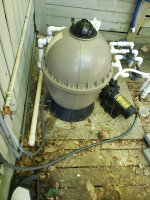
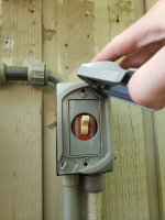
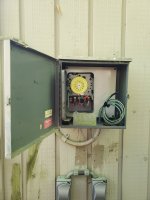
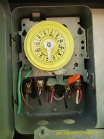
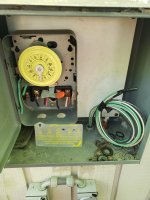
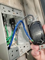
Hi everyone, so previous house owner had this mechanical timer and it worked great till one day the pump failed and the wires burned up going to the back of the pump. My dad had an electrician come and evaluate and they ended up running a dedicated line from the main to these two switches. One powers the pool pump and the other powers our booster pump. Well unfortunately the electrician decided not to hook back up our timer. So my question is what would it take to run the wires from Toggle to Timer. The switch on the right is the pool pump and the switch on the left is the booster. Here's our timer. Any insight would be helpful thank you!

Toggle switch to mechanical timer
- Thread starter Americannoli
- Start date
You are using an out of date browser. It may not display this or other websites correctly.
You should upgrade or use an alternative browser.
You should upgrade or use an alternative browser.
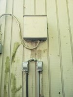
The panel doesn’t look like it’s part of the circuit. It looks like he ran a new conduit directly to the switches and from there to the pumps. The intermatic you have appears to be broken. I would mount two intermatic timers above the switches.
Sounds good, sounds like I'd just have to extend/run some wires from each switch to each timer then if I were to install a timer above each switch? Appreciate your insight!The panel doesn’t look like it’s part of the circuit. It looks like he ran a new conduit directly to the switches and from there to the pumps. The intermatic you have appears to be broken. I would mount two intermatic timers above the switches.
If you need further help post pics of the breakers and the wiring inside switches. If it’s 120v or 240v will determine the intermatics.
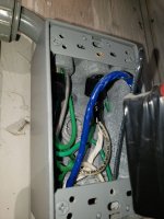
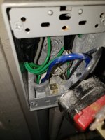
Where are the switches getting their power now? Seeing white wires in the box seems to indicate that 120V is being used.Hi everyone, so previous house owner had this mechanical timer and it worked great till one day the pump failed and the wires burned up going to the back of the pump. My dad had an electrician come and evaluate and they ended up running a dedicated line from the main to these two switches. One powers the pool pump and the other powers our booster pump. Well unfortunately the electrician decided not to hook back up our timer. So my question is what would it take to run the wires from Toggle to Timer. The switch on the right is the pool pump and the switch on the left is the booster. Here's our timer. Any insight would be helpful thank you!
That clock won't work with 120V, someone used a water-heater timer (a T-104M [240V] with a movable handle that usually sticks through a slot in the doorof the indoor box) and mounted it in a bigger outdoor box. You would need a second timeclock to control the booster properly.
If you have 240V, the power that supplies the switches would go to terminals 1 and 3 on the time clock. Wires from 2 and 4 would go to the pump. If you don't want a second timer which you should have), those wires could also go to the line side of the switch for the booster.
To wire a second timer is more complicated and may take an electrician to understand a diagram.
If you need further help post pics of the breakers and the wiring inside switches. If it’s 120v or 240v will determine the intermatics.
Yes further help would be appreciated! Here's pictures of how everything is wired and works. In the main breaker box the pool pump has one switch and the booster pump has one switch. They are both separate as I can turn off one breaker and still have the other pump run. I've also included pictures of the wiring inside the switch. The old box might have been a 240v but the electrician completely removed all the wiring and ran their own line under the walkway. Furthermore, each pump is set to the 115v option within the motors. Hopefully this provides some valuable information!Where are the switches getting their power now? Seeing white wires in the box seems to indicate that 120V is being used.
That clock won't work with 120V, someone used a water-heater timer (a T-104M [240V] with a movable handle that usually sticks through a slot in the doorof the indoor box) and mounted it in a bigger outdoor box. You would need a second timeclock to control the booster properly.
If you have 240V, the power that supplies the switches would go to terminals 1 and 3 on the time clock. Wires from 2 and 4 would go to the pump. If you don't want a second timer which you should have), those wires could also go to the line side of the switch for the booster.
To wire a second timer is more complicated and may take an electrician to understand a diagram.
Attachments
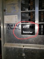
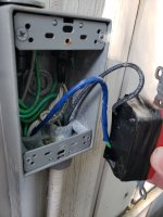
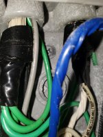
Looks like the electrician didn't know how to wire a pool for 240V. Also, those should be ground-fault circuit breakers to meet code and putting blue tape over a green wire is not wise.
You would need 2 T-101R timers, 120V timers. One for the pool pump and one for the booster.
You would need 2 T-101R timers, 120V timers. One for the pool pump and one for the booster.

shame on this electrician for his wire color selection and not upgrading the breakers or converting to 240v.My dad had an electrician come and evaluate and they ended up running a dedicated line from the main to these two switches.
You should only continue if you are confident around high voltage and a multimeter. Otherwise have a different qualified electrician out.
It won’t be a simple job for the inexperienced.
Alright sounds like a plan. So I would remove the switches and replace them with the timers? So it would be Main Power > Timer > Pump and I should check the breakers and make sure they are ground faults to meet code. Is there anything else I should do?Looks like the electrician didn't know how to wire a pool for 240V. Also, those should be ground-fault circuit breakers to meet code and putting blue tape over a green wire is not wise.
You would need 2 T-101R timers, 120V timers. One for the pool pump and one for the booster.
Gotcha so never call that electrician ever again. I thought it looked nice at first from the outside but I'm glad you guys have enlightened me with what he has done. I'm relatively new at electrician work I've done it on cars and I've got the tools so I'll probably take a crack at it. Thank you for your insight as well.shame on this electrician for his wire color selection and not upgrading the breakers or converting to 240v.
You should only continue if you are confident around high voltage and a multimeter. Otherwise have a different qualified electrician out.
It won’t be a simple job for the inexperienced.
You can remove switches and replace with timers or use an offset nipple and mount timers above switches. Blue and gray look like the hots. Grab a stupid stick(non contact tester) and some 12awg solid(black,white,green) should be fine.
Thread Status
Hello , This thread has been inactive for over 60 days. New postings here are unlikely to be seen or responded to by other members. For better visibility, consider Starting A New Thread.