The timer model should be printed on the back of the mechanism. Take a look at this link for directions on how to remove the mechanism. Confirm that power is off before handling the timer.
The following steps show you how to replace the T104 Mechanism.

www.inyopools.com
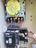
It does look like a T-104 wired for 240 volts. Line voltage from the breaker goes to Terminals 1 and 3 and are always hot. The second set of wires connected to these terminals go the pump which receives constant power. Terminals 2 and 4 are load and are controlled by the timer. Your SWG (set up for 240 volts) should be connected to these terminals. Each component should have a green ground wire. Try to trace it to the wires back to the breaker and components to which they are connected to confirm.
It is a good idea to set up the swg on a timer that will resync time after power outages. There are non-wifi digital timers that would work for that, as shown in your link, or Wi-Fi devices that you could control with an app. Any idea which direction you want to go?