- Nov 30, 2022
- 2
- Pool Size
- 7500
- Surface
- Fiberglass
- Chlorine
- Salt Water Generator
- SWG Type
- Autopilot Digital Nano+ PPC2
Hi there, I have a few general questions regarding SWG’s.
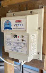
First, I have AutoPilot Cubby with an AC5 salt generator cell. This is the analogue precursor to the AutoPilot Nano.
It has stopped generating chlorine, and the blinking pattern doesn’t match that in any of the troubleshooting documentation that I’ve been able to find.
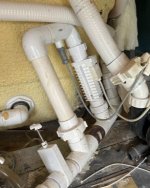
My first general question is about the flow sensor. It’s a two wire cable and a very small, so I believe it just contains a flow switch, no other sensors. The flow switch appears to be something like a reed switch that’s closed by a magnet on the vane when the water is flowing through the pipe. Is that all this is? Is it just a “open/closed” switch that provides an open or closed contact to the control panel – it’s not a Hall effect sensor is it?
If so, as part of a testing regime I should just be able to jumper the contacts on the bottom of the control panel to make it look like there is water flowing through the system, correct?
I’m not planning on doing this for any significant length of time, it’s just part of a test.
My second question is what should the DC output voltage to the RC5 salt generator cell be? Am I expecting 10V, 20V, 30V? Does anyone have any idea?
And my third question would be; does anyone have a schematic for the old Cubby, AquaCal/Autopilot control unit?
My thanks to anyone who can offer any help or information.
First, I have AutoPilot Cubby with an AC5 salt generator cell. This is the analogue precursor to the AutoPilot Nano.
It has stopped generating chlorine, and the blinking pattern doesn’t match that in any of the troubleshooting documentation that I’ve been able to find.
My first general question is about the flow sensor. It’s a two wire cable and a very small, so I believe it just contains a flow switch, no other sensors. The flow switch appears to be something like a reed switch that’s closed by a magnet on the vane when the water is flowing through the pipe. Is that all this is? Is it just a “open/closed” switch that provides an open or closed contact to the control panel – it’s not a Hall effect sensor is it?
If so, as part of a testing regime I should just be able to jumper the contacts on the bottom of the control panel to make it look like there is water flowing through the system, correct?
I’m not planning on doing this for any significant length of time, it’s just part of a test.
My second question is what should the DC output voltage to the RC5 salt generator cell be? Am I expecting 10V, 20V, 30V? Does anyone have any idea?
And my third question would be; does anyone have a schematic for the old Cubby, AquaCal/Autopilot control unit?
My thanks to anyone who can offer any help or information.