Pump stopped working!

603,

The first thing to check is to see if the pump is getting AC power.. Most pool pumps get their power from some type of timer and the timer gets the power from a circuit breaker at the equipment pad, or from the house main circuit breaker panel..

Thanks,

Jim R.
 
Thanks, the impeller moved freely when the other half checked it, I'll pull out my volt meter when I get home to make sure the pump is getting power, but I was told the timer was still working. The power flows from our main house circuit breaker box to the timer and then to the pump.
 
A,

Usually when the pump will not start it is the starter cap.. Most of the time this will make the pump humm... But it might be worth a try cost wise.. before buying a new pump..

Not sure what else you can do..

Thanks,

Jim R.
 
Bummer, well we've been thinking about upgrading to a 2 speed pump anyway I just thought we'd have longer before this one died. I have no idea how old this one is, but it came with the house and we've lived her a few years now.

I also just looked it up and living in California means we're not allowed to buy a new single speed pump or single speed replacement motor so we'd be forced to upgrade anyway.

Any recommendations on a new pump? I think a 2 speed is all we'll need. We don't have any fancy features on our pool, the spa is not attached. It's has one skimmer and one main drain that are tied together underground somewhere with no way to control how much suction is coming from each.
 
Look up rebates in your area from your power company for a variable speed. With a rebate and savings from not having to install a second timer, you might find the price difference between the two negligible.
 

Enjoying this content?

Support TFP with a donation.

Give Support
From InyoPools:
As a result, we no longer will ship single speed pumps or replacement motors to pool owners in California. This also means that if you currently own a single speed motor, be prepared to replace it with a variable speed option.

 
I was originally going to use my multimeter, but the wires are not that easy to get to so I opted for my voltage tester pen instead (it beeps and flashes a red light if you hold it up to a live wire). I tested the black wire between the timer and the pump. When the switch was on it had power, when the switch was off it did not.

The wires are run through conduit tubing so I think I would need to take the pump housing off to do more specific testing at the motor itself, but I confirmed that the wire supplying electricity to the pump was receiving power.
 
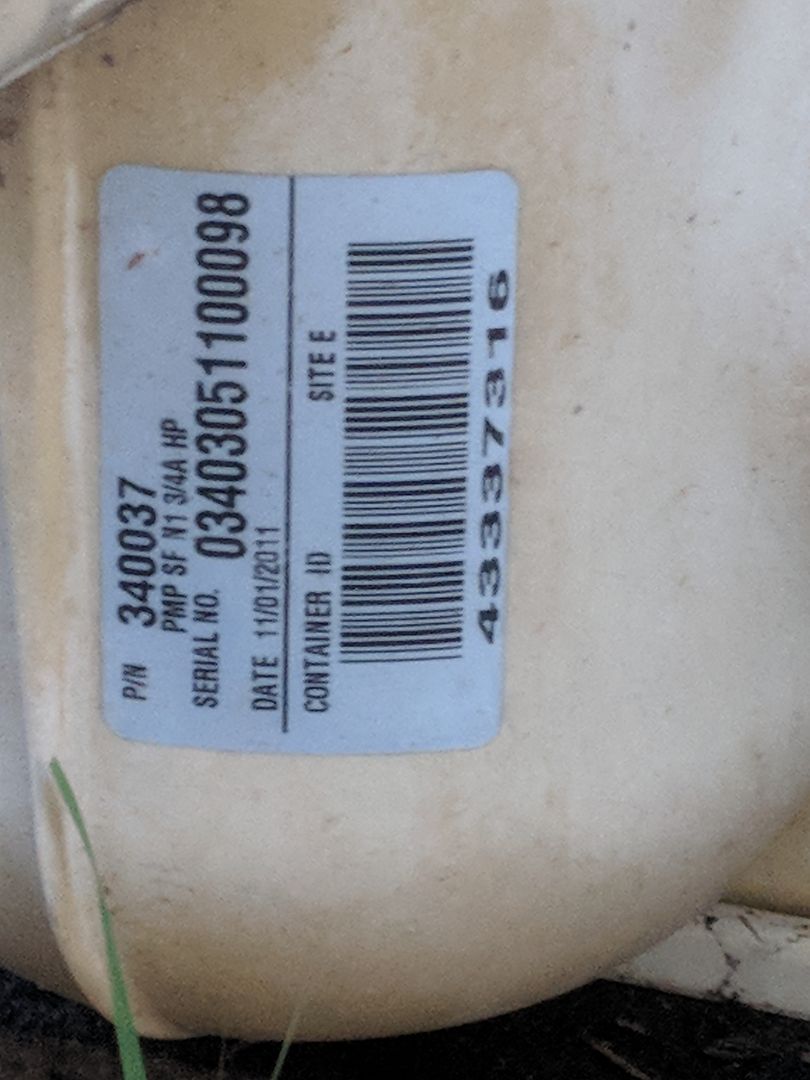
Ok, so the pump is about 7 years old.

That's not too bad.

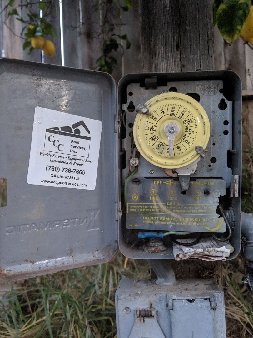
The timer looks like you're set up for 230 volts.

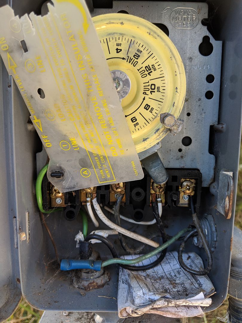
If you remove the translucent plastic cover with the yellow writing, you can use your multimeter to measure the voltage there. Just pull on the right side and rotate the clear cover on the remaining left connector. Be careful because you have live power under the cover.

Incoming power goes to terminals 1 (line) and 3 (line). If you measure voltage from 1 to 3, you should read 220 to 240 volts.

Power out to the pump goes to terminals 2 (load) and 4 (load). When the timer is off, there should be no voltage.

When you move the timer to "On" you should read 220 to 240 volts from terminal 2 to 4.

I suspect that the problem is probably with the timer or the switch between the timer and the pump.

Note: Power coming into a switch is called "Line" and power leaving a switch is called "Load".
 
Last edited:
If you don't have 240 volts to 1 and 3, the problem is with the breaker.

If you have 240 to 1 and 3 but not 2 and 4 with the timer on, the problem is with the timer.

If you have 240 on 2 and 4, you will have to check for voltage directly on the pump motor terminals.

If voltage is not getting to the pump, the problem is with the switch between the timer and the pump.

If voltage is getting to the pump, I would replace the capacitor before concluding that the pump was dead.

If you can post a picture of the breaker, and the wiring in the timer, that would help.
 
I tested the voltage across 1 and 3, then 2 and 4 (switch on), both were around 245 V. Next step is taking the pump housing off and testing things in there right?

Not sure it matters at this point, but here are the requested pictures of the breaker and switch wiring.


Enjoying this content?

Support TFP with a donation.

Give Support
Thread Status
Hello , This thread has been inactive for over 60 days. New postings here are unlikely to be seen or responded to by other members. For better visibility, consider Starting A New Thread.