Plumber left out the check valve on the heater bypass

It is interesting that Jandy has two different check valve Installation documents with different diagrams...


1672629791725-png.467338


View attachment 467462

The RIGHT diagrams agree but the WRONG diagrams are different.
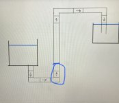
That's very interesting. The "wrong" diagrams in the second chart are wrong because the check valve would stop the intended flow completely, and only allow the unwanted backflow. The "wrong" diagrams in the first chart will allow intended flow, but might fail stopping backflow if the spring fails. So what was Jandy really trying to warn against?

All I know for sure is that both of mine are horizontal, with the clear face facing up, and the flapper on the correct side (flow-wise). They'll work with or without the spring.
 
Ha, it gets even more convoluted. In one of Allen's links, the text reads:

"Check valve can be installed in horizontal or vertical piping runs, with the flow running upward."

The other link reads:

"The Check Valve can be installed in horizontal piping runs or vertical piping runs with the flow running upward."

The first line has a comma, which really confuses the issue. I believe the second line is what Jandy intended: either install it horizontally, OR vertically as long as the water flows from the bottom up. There's another instruction that gives another clue:

"For optimal sealing, place check valve at lowest elevation possible in plumbing system, so weight of water column can help seal it. Jandy recommends a water column with a minimum height of 18"."

I think there they're talking about when the pump is off, the water above the check valve will press down on the flapper, keeping it closed and ready for the next pump run.

Diagrams aside, I think both sets of instructions are about helping the flapper do its job, even when the spring is not doing so.
 
  • Like
Reactions: JamesW
I think there they're talking about when the pump is off, the water above the check valve will press down on the flapper, keeping it closed and ready for the next pump run.

Diagrams aside, I think both sets of instructions are about helping the flapper do its job, even when the spring is not doing so.

We see many new pools with the flapper check valve installed on the vertical spa return pipe with downward water flow.

We also hear about many folks complaining that their spa is draining in spite of having replaced the check valve.

I think we may now understand where many of the spa draining problems are coming from.
 
  • Like
Reactions: JamesW and Dirk
The fix is pretty simple, actually. The plumber can cut out the elbow between the 3-way and the check. He'd make the cuts right up next to the ports. Then connect the check horizontally to the three-way with a coupler (one size larger, so the coupler would go over the outside of the ports). Then 90° down, then jog back over to the existing vertical pipe. The jog can be underground and won't ever be seen again once backfilled...
 
  • Wow
  • Like
Reactions: Dunn08 and JamesW
That is interesting. Although both instructions share the same verbiage “Can installed vertical with water flowing upwards.”

All 6 examples of “wrong” make complete sense though. They’re probably tired of getting phone calls from people thinking there valve isn’t working when they actually installed it without the flapper at the water entry point.

For optimal sealing, place check valve at lowest elevation possible in plumbing system, so weight of water column can help seal it. Jandy recommends a water column with a minimum height of 18"."

I think there they're talking about when the pump is off, the water above the check valve will press down on the flapper, keeping it closed and ready for the next pump run.

Diagrams aside, I think both sets of instructions are about helping the flapper do its job, even when the spring is not doing so

Exactly. The same reason that almsot any horizonal bolt you will ever see on a fixed wing aircraft is oriented forward to aft.
 
Last edited:
We also hear about many folks complaining that their spa is draining in spite of having replaced the check valve.

I think we may now understand where many of the spa draining problems are coming from.

Researching that exact topic is what sent me down this rabbit hole in the first place. Trying to educate myself in case it happens to me. At least this can be added to the troubleshooting tree.
 
If you have two bodies of water at different heights, which check valve will be most reliable and why?

View attachment 467505

I’ll play.
This one. When the pump turns off it will have the most standing water sitting on the flap, helping it seal. Also, gravity.
 

Attachments

  • 644F1732-9E91-4E90-B98B-34D3638E748E.jpeg
    644F1732-9E91-4E90-B98B-34D3638E748E.jpeg
    737.1 KB · Views: 5
The water pressure holding the flapper closed for each check valve is determined by the difference in surface level (H).

So, there is no difference in water pressure holding the flapper closed regardless of where the flapper is.

The weight of the flapper is very low in water.

If we assume that the density of the flapper is 2 X that of water, then the flapper weight is about equal to the amount of water it displaces, which is pretty low.

The spring tension exerts much more force on the flapper than the weight of the flapper.

If the water height is about 3 feet difference (1.3 PSI) and the spring adds another 0.5 psi, that is 1.8 psi.

If the flapper has a surface area of 7 square inches, then the water pressure plus the spring is exerting 12.6 lbs of force on the flapper to keep it closed.

The flapper might weigh 0.1 pound in water, which means that the check valves pointing up have slightly more force holding the flapper closed due to the weight of the flapper compared to the horizontal check valve and the check valves pointing down will have slightly less force than the vertical pointing up or the horizontal check valves.

Pointing up = 12.7 lb.

Horizontal = 12.6 lb.

Pointing Down = 12.5 lb.

The force on the flapper pointing down is 98.4% of the force on the flapper pointing up.

1672712823172.png
 
Last edited:
For a horizontal check valve, the flapper only has weight going straight down.

So, F2 is zero because there is no force pointing in the horizontal direction to keep the flapper closed.

It will fall to the vertical (Closed) position, but there will be no closing force exerted by the weight of the flapper.

1672713545460.png
 

Enjoying this content?

Support TFP with a donation.

Give Support
The check valve flapper has two forces acting on it.

F1 is determined by H1 and F2 is determined by H2.

So, the net force is F1 - F2, which is determined by H3 (H1 - H2).

It does not matter where the check valve is in the plumbing because the net force on the flapper is exactly the same.

The only values that change are F1 and F2, but F1 - F2 is always the same number.

1672755831264.png
 
Last edited:
Thread Status
Hello , This thread has been inactive for over 60 days. New postings here are unlikely to be seen or responded to by other members. For better visibility, consider Starting A New Thread.