I'm planning a two-phase pH project.
Phase 1 is the pH probe manifold. I'm planning to get the probe readings and I'll manually evaluate what it takes to drive the pH down. The reading will be processed with an Arduino or ESP. I'm good with the C/C++ code.
Phase 2 is to evaluate the reading and act with an acid feeder pump. I've already decoded and am reading the RS-485 bus so I can tell, among other things, if the pump is on or not, and what RPM it's at, so for phase 2 this will prevent feeding into an idle system.
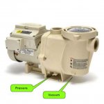
So what I am looking for are images and ideas for probe manifolds. The probe I'm looking at can handle 100psi, so no issue there, but flow can be rough on the sensing element, so low flow would be ideal. I have drain plugs on the bottom of the pump basket and on the impeller housing. I assume the basket plug is vacuum but I don't know about the impeller housing plug. The pump is an IntelliFlo VS-3050. I was thinking about using one of the drain plugs on the pump body to tap for flow, but where to connect the other end is another point to work out. Maybe the aerator return line, but that would require a pressurized source tap and would make the fitting under the coping ooze effluent.
So let's see those manifolds and ideas on where to source and drain the effluent!
Thanks.
Phase 1 is the pH probe manifold. I'm planning to get the probe readings and I'll manually evaluate what it takes to drive the pH down. The reading will be processed with an Arduino or ESP. I'm good with the C/C++ code.
Phase 2 is to evaluate the reading and act with an acid feeder pump. I've already decoded and am reading the RS-485 bus so I can tell, among other things, if the pump is on or not, and what RPM it's at, so for phase 2 this will prevent feeding into an idle system.
So what I am looking for are images and ideas for probe manifolds. The probe I'm looking at can handle 100psi, so no issue there, but flow can be rough on the sensing element, so low flow would be ideal. I have drain plugs on the bottom of the pump basket and on the impeller housing. I assume the basket plug is vacuum but I don't know about the impeller housing plug. The pump is an IntelliFlo VS-3050. I was thinking about using one of the drain plugs on the pump body to tap for flow, but where to connect the other end is another point to work out. Maybe the aerator return line, but that would require a pressurized source tap and would make the fitting under the coping ooze effluent.
So let's see those manifolds and ideas on where to source and drain the effluent!
Thanks.