Pentair easytouch has no power.

Pure_American_metal

In The Industry
Nov 10, 2022
10
California
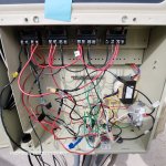
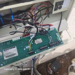
Hey guys, I have a pentair easytouch panel that has no power going to it whatsoever. Not the breakers or the mains.

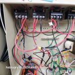
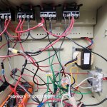
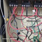
There is still power coming into the unit. From the main breaker. I am testing voltage on the line side of the relays and they have power.
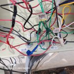
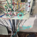
I rewired a lot of it. The wiring the prior guy had before me was pretty mickey mouse. It wasn't any loose connections.
Although.
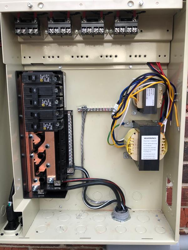
There is a pump, heater, the panel , and the lights and blower all run off one breaker that comes from the mains power.
There is no sub panel built into the side of the pool panel.
Would it be an overload issue?


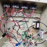
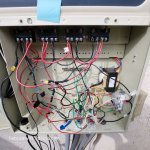
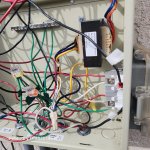
My guess is either it's the transformer or the whole board is bad.

Any suggestions on how to proceed? How would I check to see for sure if it is the transformer. Or the board.
 
PAM,

Use a voltmeter and measure between L1 and L2 where the 240 Volts AC is connected to the load center and tell me if you get 240 volts or not. Do NOT measure L1 to ground and L2 to ground. I only want to know what you get between L1 and L2.

Sometimes idiots will wire the system transformer through the GFCI receptacle in the bottom left of the cabinet. It is worth a second just to make sure the GFCI is not popped.

Show me several pics of the inside of your EasyTouch showing the wiring, the relays, and the load center, etc.

Thanks,

Jim R.
 
The problem is is there is no load center inside the panel it's all run off one breaker at the mains panel All these relays are jumpered together from both hots coming in from said single breaker.

A lot of the grounds are all hogtied in together and run into the ground post on the back of the panel.

The two mains power lines that are coming in I've wrapped those both in a strip of yellow tape so you know those are the two power lines coming in.
The transformer is wired up for 120 yellow wire is isolated.

All the neutrals are again tied in together One comes from the GFCI power outlet one from the lights and the other from the transformer and then there's another neutral coming to this cable that I'm not quite sure what it goes to and I can't figure it out it goes from here to underground.
 

Attachments

  • 16766703977977251370266481544083.jpg
    16766703977977251370266481544083.jpg
    459 KB · Views: 14
  • 16766704245758268462251500450519.jpg
    16766704245758268462251500450519.jpg
    493.4 KB · Views: 12
  • 16766704523637342233981955857898.jpg
    16766704523637342233981955857898.jpg
    480.7 KB · Views: 11
  • 16766710625806794672896957282744.jpg
    16766710625806794672896957282744.jpg
    510.2 KB · Views: 10
  • 16766710796006997483239454940153.jpg
    16766710796006997483239454940153.jpg
    522.9 KB · Views: 11
  • 16766710891613537208324391618462.jpg
    16766710891613537208324391618462.jpg
    502.5 KB · Views: 13
  • 16766711338086822872391541022968.jpg
    16766711338086822872391541022968.jpg
    575.2 KB · Views: 14
  • 16766711608996954387279559329068.jpg
    16766711608996954387279559329068.jpg
    497.7 KB · Views: 11
  • 20230217_140244.jpg
    20230217_140244.jpg
    544.9 KB · Views: 12
  • 16766715078877814836096043673601.jpg
    16766715078877814836096043673601.jpg
    554 KB · Views: 16
So from both halves of the phase coming in from the mains I'm measuring 240 on both line one and line two. There's two other red and blacks coming out of the mains conduit line. I'm not 100% sure what it is I think it's the blower honestly. And then there's a neutral line coming out of the conduit straight into the GFCI outlet.


Like I said I'm able to run the pump right now because it is getting power and the pump is wired up to wine one and two on the first relay the same one that the mains power is wired up to. And like I said it's all jumpered from that first relay all the way down
 
Here's where it gets interesting is where the neutrals are all hogtied in together and where all the "120v" tie ins are together as well I'm reading the voltage between the "neutral" lines and what I know for sure is 1/2 of the phase of hot but it's reading zero volts. I'm wondering if the neutral is somewhere along the line tied into the same half of the phase?
 
That's the goofiest wiring I have ever seen.

Very unprofessional.

I would install the load center base and have an electrician add breakers and rewire everything.


16d616dd-deda-5d0f-87e6-e1b4b8ce9dfb
 
Last edited:
The problem is is there is no load center inside the panel it's all run off one breaker at the mains panel All these relays are jumpered together from both hots coming in from said single breaker.

A lot of the grounds are all hogtied in together and run into the ground post on the back of the panel.

The two mains power lines that are coming in I've wrapped those both in a strip of yellow tape so you know those are the two power lines coming in.
The transformer is wired up for 120 yellow wire is isolated.

All the neutrals are again tied in together One comes from the GFCI power outlet one from the lights and the other from the transformer and then there's another neutral coming to this cable that I'm not quite sure what it goes to and I can't figure it out it goes from here to underground.
Very scary wiring. Each ground wire should be attached to the ground bar, not a WAGO (and the WAGO should at least be a green one for grounds). Bad practice. Why so many splices? One has failed at some point according to the first picture in the series. Why are there 3 wires in terminal #1 of relay 1? Please, listen to JamesW before someone gets hurt.
 
I suspect that EasyTouch panel had replaced a Jandy Aqualink.

I guess that by all the wires that were too short and needed splices to read the relays, ground bar, and neutral bar. I had that problem when I replaced my Aqualink with an IntelliCenter. The Jandy layout is different with the ground par and neutral bar at the bottom on the cabinet instead of Pentair in the middle. And the Pentair cabinet is longer so the length from the bottom to the relays is greater.

I think the way to fix your problem is to cleanup the wiring and you will find the problem in the process.
 
PAM,

It appears to me you have a 'lite' version of the EasyTouch. It has no load center and a max of 4 schedules (Including any egg timers not set to the default of 12 hours and only two feature circuits.

It appears to me that you have a VS pump.. Are you running the pump using the Pump's control panel?

I can't tell where all the wires go as there are just too many of them for my old eyes.

If this were my system, the first thing I'd want to know is does the GFCI outlet work. Plug in a light or drill and see if it works. If not reset it and see what happens.

The next thing I'd do is to ensure that the system transformer has 120 volts when you measure between the black (hot) wire and the Violet (Neutral) wire going into the system transformer.

Do you also have ScreenLogic??

Thanks,

Jim R.
 

Enjoying this content?

Support TFP with a donation.

Give Support
I agree start fresh. You have your power going in one leg on the line side and the other on the load side. Same thing with the heater. Your transformer is hooked up on jumpers that interweave line load back and forth etc. you have 120v pulling from the 240v circuit. Best to pull everything find out where everything comes and goes. Having a load center makes it cleaner.
 
Last edited:
Gentleman I figured it out.

The neutral line coming out of the mains was going into the GFCI. And that was a stopping point. All the other neutrals for 120 were wired together but did not connect with the mains neutral
Very scary wiring. Each ground wire should be attached to the ground bar, not a WAGO (and the WAGO should at least be a green one for grounds). Bad practice. Why so many splices? One has failed at some point according to the first picture in the series. Why are there 3 wires in terminal #1 of relay 1? Please, listen to JamesW before someone gets hurt.
 
PAM,

It appears to me you have a 'lite' version of the EasyTouch. It has no load center and a max of 4 schedules (Including any egg timers not set to the default of 12 hours and only two feature circuits.

It appears to me that you have a VS pump.. Are you running the pump using the Pump's control panel?

I can't tell where all the wires go as there are just too many of them for my old eyes.

If this were my system, the first thing I'd want to know is does the GFCI outlet work. Plug in a light or drill and see if it works. If not reset it and see what happens.

The next thing I'd do is to ensure that the system transformer has 120 volts when you measure between the black (hot) wire and the Violet (Neutral) wire going into the system transformer.

Do you also have ScreenLogic??

Thanks,

Jim R.
Hey thanks I actually was able to locate what the problem was and get it rectified. I told my uncle he would be better off to install a load center inside the panel.
 
Thread Status
Hello , This thread has been inactive for over 60 days. New postings here are unlikely to be seen or responded to by other members. For better visibility, consider Starting A New Thread.