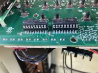
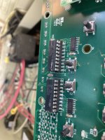
Pentair EasyTouch "3amp 12v electronics" stays tripped

Oct 18, 2022
15
Central Caifornia
hi team... did quite a bit of reading before i decided to post. So ill give to low-down, then what i did from prior thread suggestions here. Context about me... i can follow directions, but not very electric savvy, not a pool guy, ive got a screwdriver and a plusivo digital multimeter (that i dont really know how to use.)

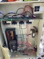
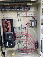
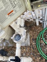
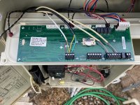
Pentair easytouch system, been working just fine. not sure age of system, bought house 4 months ago. went out of town, came back and noticed pool looked dirtier than it should. went to manual start the egg-timer sequence. nothing. no lights, no led, and noticed the 3amp "12v electronics blu/wht" mini breaker tripped. I reset the button, the panel lights flicker for a half second, and immediate trip again. Nothing on led screen, no lights on panel, zero function. We had no weather incidents, no power outages, and nothing otherwise looks disturbed. Pump will run fine when taking the EasyTouch out of the equation.

Wake up this morning and do some good reading on here, along with a good once-over. No obvious scorch of burn marks.
So this is what ive done, based exclusively on some prior threads and discussions here, as i would have no idea to try these otherwise
Check all main breakers. nothing tripped, but i cycled them off/on anyway. The GFI outlet on the side of panel works.
I disconnected everything on the back of the board EXCEPT the power (6pin dark plug on right side), mini breaker still tripped immediately
I removed the 2 ULN2803a transistor deals, mini breaker still tripped immediately

From previous... it sounds like either the transformer, or actual board is toast...?
Any other suggestions are appreciated. I am not sure how to determine which of the 2 it could be. again, i have a cheap plusivo multimeter with 2 prongs, and some aligator clip attachments if that helps in any way.
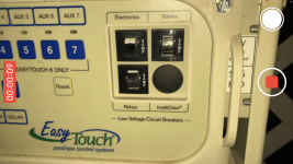
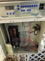
Photo Oct 17, 9 42 25 PM.pngPhoto Oct 18, 10 40 48 AM.jpgPhoto Oct 18, 10 40 40 AM.jpgPhoto Oct 18, 7 36 38 AM.jpgPhoto Oct 18, 10 41 42 AM.jpgPhoto Oct 18, 7 36 45 AM.jpgPhoto Oct 18, 7 36 25 AM.jpg
 
T,

Does the breaker trip when J1 (power plug) is removed from the main board?

If not, and it does trip when J1 is plugged into the main board, but everything else is unplugged, then most likely the main board is bad.

My guess would be one of the voltage regulators has bit the big one.

Let's see if Tom has any ideas for ya'. Calling @ogdento

Thanks,

Jim R.
 
hey they're probably fine but let's just check to make sure your transformer voltages look okay...

- unplug the power connector from the board
- set your multimeter to ac volts (if it's not auto-ranging set it to the first range greater than or equal 30)
- there are 3 pairs of wires on the transformer (blue, orange and red)... blue pair supplies 14vac, orange pair supplies 21vac, and red pair supplies 29vac
- put a probe on the connector pins for each pair and you should get around 14vac, 21vac and 29vac respectively, +/- a volt or so

if that checks out ok then i'm inclined to agree with Jim... remove the board, flip it over and check the two bridge rectifiers to see if one of them looks toasty. if you want to, you can google how to test a shorted rectifier (it'd be better than me explaining here)

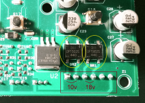
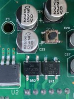
Here's a picture showing the rectifiers (the leftmost yellow circle shows rectifier BR2 for the 12v supply), this is where the blue pair connects and is converted to dc (about 16volts) for driving all the on-board electronics and powering devices connected to the comm port (red/black terminals).

 
Last edited:
@Jimrahbe that's an excellent question ;)

I goofed and pasted in a photo of an intellitouch mainboard instead of an easytouch. There would normally be an inductor there but lightning strike blew up a few parts, including the original inductor... so I just jumpered it to get it running.

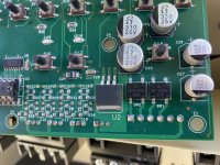
Here's the picture I meant to include (newer system transformers have a 10vac output rather than 12, which might be confusing because this is where the blue pair - that will measure as 14vac - connects. the rectifier and the large capacitors boost it up to about 17vdc. the 3-pin + tab chip to the left is a 5 volt regulator to power the onboard logic chips)

easytouch rectifier connection.png
 
  • Like
Reactions: thatoneguy3000
Hey @thatoneguy3000, just wanted to say that you're in good hands with Tom and Jim. They know their stuff. And to welcome you to TFP!

For someone that describes himself as "not very electric savvy," I gotta say you've done a heck of a job troubleshooting so far, along with posting all those pics and doing all that research. Well done. Here's hoping you find a quick solution!
 

Enjoying this content?

Support TFP with a donation.

Give Support
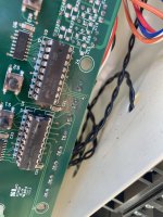
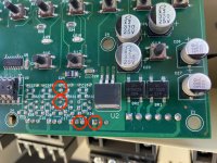
Ya got bugs! (Or something.) I couldn't say if that's the problem, but they can't be helping! They definitely caused some shorts, for however briefly.

@ogdento might know if that could have permanently damaged the board. But also consider they might have gotten into something else that did.

Photo Oct 19, 10 21 41 AM.jpg
 
Last edited:
@Dirk nice catch on the bugs, I didn't see those. the ones you circled are on/around the actuator relays which would be connected to the 18vac supply (powers the relay drivers) and the 24vac supply (powers the actuators)... so they probably didn't hurt the 12v supply (powers the board and comm port devices), but there could be more?

@thatoneguy3000 those readings tell me your transformer is ok :) but the problem is likely with the board :(

since the board pops the 12v breaker, then it's drawing over 3amps... there could be a short in one or more components that either make up, or are connected to the 12v supply. we can check to see if there's a short from power to ground by testing the voltage regulator (with everything still disconnected!). the regulator is U2 in the photo above, a 3-pin LM1804 device. You'll see a dot on the rightmost pin... that's pin 1 (aka adj/gnd). pin 2 in the middle is the output, and pin3 is the input. we're going to see if there's a short from either the input or output to the ground pin... and if we find one, then we know what's wrong but the short might not be in this device!

try this with your multimeter:
- set the meter to the continuity function (once set, you'll hear a beep if you touch the probes together)
- now put one probe on pin1 and the other on pin2... leave the probe on pin1 and move the other to pin3... do you get a beep on either pin?
 
one other thing... i zoomed in on the photo and there is corrosion on the +/- pins of BR1 (this is not the 12v supply... it's connected to the 18v breaker) but some of the other pins on various devices appear to have corrosion as well. give the board a good inspection with a magnifier and see if there's much more
 
one other thing... i zoomed in on the photo and there is corrosion on the +/- pins of BR1 (this is not the 12v supply... it's connected to the 18v breaker) but some of the other pins on various devices appear to have corrosion as well. give the board a good inspection with a magnifier and see if there's much more
1&2 = no tone
1&3 = good tone

also, not really sure what i'm looking for, but these look maybe corroded/dirty?

Photo Oct 20, 9 52 40 AM.jpgPhoto Oct 20, 9 52 21 AM.jpg
 
you can also do that continuity check on the +/- pins of the rectifier.

if you don't get a beep there, check out this short video on how to test a bridge rectifier...

a short will show 0.000 on your meter (no voltage drop)... it's nice to know that it's actually shorted before you try to pull it off
 
ok so not sure if i did this right... my mutimeter has what lookslike diode test symbol and the tone, on the same spot. so, this is what i did... i tested each of the 4 pins against each other ones, 1&2, 1&3 etc... these are the results. for reference, my assignemt of pins 1,2,3,4 is shown in picture. the results indicated either a tone or not, and a number reading:

Pins:
1&2 = tone & 006
1&3 = no tone & 684
1&4 = no tone & 688
2&3 = no tone & 671
2&4 = no tone & 680
3&4 = no tone & 1186

so, +&- pins i believe were only ones WITH tone...? so no short?
Photo Oct 21, 7 37 54 AM.jpg
 
Pins:
1&2 = tone & 006
1&3 = no tone & 684
1&4 = no tone & 688
2&3 = no tone & 671
2&4 = no tone & 680
3&4 = no tone & 1186
Please specify where was the red and black lead of the multimeter.
e.g. if red 1 and black 2 = .006 then its shorted
but if black 1 and red 2 = tone then its ok
 

Enjoying this content?

Support TFP with a donation.

Give Support
Thread Status
Hello , This thread has been inactive for over 60 days. New postings here are unlikely to be seen or responded to by other members. For better visibility, consider Starting A New Thread.