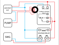
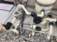
My wiring diagram for current sensing relay

2¢. Personally, I'd feel safer using a flow switch over a current sensing relay. The latter detects when the pump is using some amount of power, not that the impeller is actually moving water through the SWG. Only a flow switch can do that. And a flow switch is much cheaper, too. If you'd care to explore this idea, I can help you with the wiring.

If you really want a safe system, you'd use both, your sensor and a flow switch.

FWIW, I say "Personally, I'd feel safer using a flow switch over a current sensing relay" because that's exactly what I did. You can read about it here, complete with the schematic I designed (my circuit does things you don't need, and the flow switch is actually protecting against acid injection, not chlorine, but the function is the same, so you'd have to wade through the parts of it that don't apply to your application).


All that said, I commend you for adding any protection at all. A lot of people don't.
That is some amazing overkill building there, and I love it.

I will be using both the flow sensor on the SWG, and this relay, together to back each other up. If one fails, the other can take up the slack until I repair the issue.
 
  • Like
Reactions: Dirk and Kaylee34
I really didn’t take time to read everything. Your pump, being a VS, has power all the time?
Correct. It’s powered on all the time, and runs at whatever speeds/times I program in the pump itself. The idea is that it only pulls amps when it’s actually running, so the relay will sense that.
 
I will be using both the flow sensor on the SWG, and this relay, together to back each other up. If one fails, the other can take up the slack until I repair the issue.
My bad! The on-board flow sensor is all you need for flow sensing. Adding the current sensing is a great additional safeguard. Well done.
 
Correct. It’s powered on all the time, and runs at whatever speeds/times I program in the pump itself. The idea is that it only pulls amps when it’s actually running, so the relay will sense that.
Are you sure that relay won’t stay energized all the time? There will always be current flowing. Just more or less.
 
Are you sure that relay won’t stay energized all the time? There will always be current flowing. Just more or less.
The relay is adjustable on how many amps will trigger it. I can dial it in so it only closes when it reaches the amps pulled by my pump at its minimum RPM. Any tiny amount of amps being pulled will be below the threshold I set.
 
  • Like
Reactions: Flboy44
The relay is adjustable on how many amps will trigger it. I can dial it in so it only closes when it reaches the amps pulled by my pump at its minimum RPM. Any tiny amount of amps being pulled will be below the threshold I set.
Folks (like me) with automation rely on a relay the controller closes when the pump is called to run. It's that relay that energizes the SWG. That and the SWG's flow sensor are my two safeguards. The controller does receive feedback from the pump that it is on, and its RPMs etc, but it doesn't really know any of that is actually true. The SWG's flow switch is the redundant safeguard that covers that issue.

But a current sensing relay is far more reliable in determining if your pump is actually powered or not. Still doesn't actually know for sure that the pump is pushing water or not, but I'd dare to say your current sensor is a "safer safeguard" than what most of us with automation rely on. Again... good job.

That all said, while I appreciate a fellow over-builder, just so we're clear, I'm the over-builder/over-thinker king around these here parts. So stay in your lane, pal! ;)
 
Last edited:
@Dirk has some really, really cool projects posted on the forum. I've read a few of them and been utterly fascinated.
Some of that stuff is completely over my head! :ROFLMAO:

If you don't have automation, or plan on having it, this really is an easy to install, budget friendly safety device. One of the key points with using a CSR is looping the wire through the sensing coil. Four loops is all I could fit, so the current sense range is reduced to 0.5 to 5 amps. From there, it is as @AW139 says, you adjust the dial to close the relay at your pump's lowest RPM.

I like the time delay feature on the relay I'm using. It keeps the SWCG from energizing immediately when the pump starts up. When the pump primes, the SWCG never powers up until I've hit full prime and the flow switch is tripped. It's also very nice when we get storms in the area and the power goes off and on every few minutes. It might give me a little added protection against surges but who knows. I like to think it does.
 
  • Like
Reactions: Dirk and AW139
If you don't have automation, or plan on having it, this really is an easy to install, budget friendly safety device. One of the key points with using a CSR is looping the wire through the sensing coil. Four loops is all I could fit, so the current sense range is reduced to 0.5 to 5 amps. From there, it is as @AW139 says, you adjust the dial to close the relay at your pump's lowest RPM.

I like the time delay feature on the relay I'm using. It keeps the SWCG from energizing immediately when the pump starts up. When the pump primes, the SWCG never powers up until I've hit full prime and the flow switch is tripped. It's also very nice when we get storms in the area and the power goes off and on every few minutes. It might give me a little added protection against surges but who knows. I like to think it does.

The relay I have defaults to a 1-10 amp adjustable range. According to my quick math, at 1700 RPM my pump should draw right around 1 amp, so even a having only two loops should get me comfortably down below my minimum. I will probably put 3 loops through it, in order to give me a nice comfortable adjustment range.

I figure maxing out the timer at 6 seconds is probably helpful too. No need for it to go on right away. Even longer would be better, since as you said it would give time to prime the pump. Depending if it's drained or not, my pump can take 10-15 seconds to prime and get water flowing normally. But I'm fairly confident that 5 seconds of SWG into the non-moving water won't hurt anything. All that said, this really only matters if the flow sensor fails. So it's unlikely to be a continuous issue.
 
Last edited:
  • Like
Reactions: Kaylee34 and Dirk

Enjoying this content?

Support TFP with a donation.

Give Support
Schematic looks right to me. Much easier to see it with the color. Nice. And now I get the debate about the second relay. It does add another component, but I think cutting both 240 legs is the right way to go.

Now he's using Illustrator?! Who does this guy think he is??!! I thought I was clear. :rant:
Oops, did I write that out loud?
 
Every now and then a thread really reinforces my decision to run the pump/swg 24/7 and not have to care about *any* of all that.

I salute you all. :salut:


Also, this is fun to follow. :epds:
 
  • Like
Reactions: AW139 and Dirk
Every now and then a thread really reinforces my decision to run the pump/swg 24/7 and not have to care about *any* of all that.

I salute you all. :salut:


Also, this is fun to follow. :epds:

I run my pump 24/7 already, but you know... overkill.

Also, occasionally the SVRS on my pump likes to decide that there is a blockage and shut off. It normally doesn't happen much now that I have tweaked it, but if something like a plastic bag were to blow into the pool and get sucked into either the intake or the skimmer, it could easily trip the SVRS, causing the pump to shut off.
 
  • Like
Reactions: Dirk and Newdude
Running 24/7 is certainly a safeguard, but on its own it's not any safer than any other single safeguard discussed in this thread. Lots of things can stop a pump and leave an SWG energized, and not just SVRS. Especially one that isn't running from automation, because its control panel is active and easily accessed. It looks invitingly like a space ship control panel, or video game controller, that some little boys or girls might find very interesting! Or maybe Bobs-yer-Uncle doesn't want to listen to the pump while he's sleeping it off, uh, I mean taking a nap, so he decides to "turn the pump down." Two safeguards is better than one!

240_F_296023769_SlekpHazZRce7hf393PhSCcdNgqw9E8S.jpg
 
Last edited:
  • Like
Reactions: Newdude
I too consider a flow switch to be a higher level of protection than pump current sensing -- there are many ways a pump could be running but mininal or no water flowing through the SWCG, from broken pipes to a faulty filter seal to a drain left open lowering the water below the skimmer, etc.

I've thought about a simple backup of a second flow switch in line, just wired in series with the first one, so either showing "no flow" would stop the SWCG. That would be dirt cheap to install. It does of course rely on the SWCG's control board sensing the no flow. I do like that the current sensor, or Dirk's flow suggestion, kills power to the SWCG control box altogether, but I'm wondering about the relative failure rates and ROI.
 
  • Like
Reactions: Dirk
I too consider a flow switch to be a higher level of protection than pump current sensing -- there are many ways a pump could be running but mininal or no water flowing through the SWCG, from broken pipes to a faulty filter seal to a drain left open lowering the water below the skimmer, etc.

I've thought about a simple backup of a second flow switch in line, just wired in series with the first one, so either showing "no flow" would stop the SWCG. That would be dirt cheap to install. It does of course rely on the SWCG's control board sensing the no flow. I do like that the current sensor, or Dirk's flow suggestion, kills power to the SWCG control box altogether, but I'm wondering about the relative failure rates and ROI.
I think without any other external factors, a flow switch would be a better choice. Like you said, it’s actually telling if water is moving or not, unlike a current relay.

The problem is that a mechanic flow switch is going to be substantially more likely to fail vs an electrical relay, and could easily fail in the “flow” position. Electrical relays are insanely reliable. To the point that as long as they are wired correctly, and don’t get physically damaged, they should last indefinitely. They are rated for tens of thousands of cycles or more, and even then will likely just fail to close the circuit, leaving the SWG un-powered. With my pump running normally all the time, the relay may only see maybe a few hundred cycles in my pools lifetime.

I also think having safety feature of different types is beneficial. We already have the flow switch mechanical safety, so let’s go with an electrical backup safety.

All in, it’s about $100 for both relays.
 
Last edited:
Ha, the flow switch I ended up using has a gauge of wire so small that I was concerned about running enough juice through it to power anything. So I designed my circuit such that the flow switch operates a relay, and it's that relay that controls power to the device.

So I have ignored the issue of which, between a flow switch and a relay, is more dependable... I'm all set to experience either failure!! ;)

I think we can all agree, redundant safeguards are the way to go...

FYI: the ideal location for a flow switch is in a vertical pipe, oriented so that in the event of no flow, gravity can pull the switch to the least dangerous position. It doesn't guarantee that the switch won't still fail in the wrong position, it just increases the chances it won't. I suspect that manufacturers that suggest installing their SWG vertically have this in mind.

Unfortunately, I didn't have a choice, so my flow switches are horizontal, both the one in my SWG and my redundant one. Oh well... do as I say, not as I do!! 🤪
 
  • Like
Reactions: AW139 and Newdude
It’s just that the diagrams shows the relay behind powered by L1 (and L2), but the relay doesn’t interrupt L1 going to the SWCG in any way. Even with the relay being in the “open” position, there is a hot wire going to the SWCG. I honestly don’t know if this is ok or not, hence why I’m implementing the second relay. I would love to find out it is ok, because it would make my wiring much simpler.
First, I am not an Electrician, and second, Canada's code may differ. Switching only one line of a 240V circuit is allowed per the code. The current sensing relay is considered a controlling device, not a disconnect. Your circuit breaker serves as the circuit disconnect. When you service the SWG you need to cut power by using the disconnect. See this thread from Mike Holt's Forum

In my opinion, having both lines switch adds complexity without any real advantages. First, it moves the "Hot Line" out of the SWG and into the box where the two relays are located. Servicing this relay box will require using the same circuit breaker. When servicing the SWG, you certainly don't want to depend on both line relays (think undetected welded contacts fault) being open, so you will still be discounting using the circuit breaker.
That's certainly logical, but it doesn't account for the sun or a dog or some other force chewing through the insulation of the SWG cable, exposing one or both 240V legs to ground (the actual ground). The SWG is powered via an insulated cable (think heavy-duty extension cord) and is not protected with conduit like you'd expect typical 120V or 240V wiring to be. So while de-energizing both legs is only marginally safer for this reason than only one leg, it is marginally safer. The danger would still exist while the SWG was powered on, but not while powered off.

Of course, if the OP leaves the SWG on 24-7, then my flimsy argument has even less merit.

I cover every inch of my pad's exposed wires in cable wrap (cables to SWG, valve actuators, temp sensors, etc), to keep the sun off of them. I keep the dog from chewing on wires by not having a dog.

wire cover.jpegpad.jpg
 
Last edited:

Enjoying this content?

Support TFP with a donation.

Give Support
Thread Status
Hello , This thread has been inactive for over 60 days. New postings here are unlikely to be seen or responded to by other members. For better visibility, consider Starting A New Thread.