Jandy Heater won't turn on --- missing its 24V from my RS Control Panel

jesse-99

Gold Supporter
Silver Supporter
Bronze Supporter
May 2, 2021
717
Illinois
Pool Size
36000
Surface
Plaster
Chlorine
Salt Water Generator
SWG Type
Jandy Aquapure 1400
Realized my Jandy Hi-E2 heater isn't even trying to turn on this morning even though I'm telling it to turn on through the iAquaLink app (and temp setting was HIGHER than the water temp). I did some troubleshooting and found this when testing voltages.

1688227980641.png

Step #1 -- I passed, 24V at transformer.
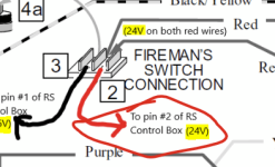
Step #2 -- I passed, 24V at the red wire terminal block
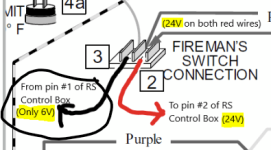
Step #3 -- I failed, only 6V at the white wire terminal block

Note -- in the above diagram it shows a BLACK jumper wire between the terminal block. I do NOT have that because I am controlling my heater via my Jandy iAqualink RS control box. (the black wire is ONLY if you have no automation/remote controlling it).

So at the fireman switch terminal block, I have this: (crude drawing, note the black/wire wires from Paint3D that I added)

1688228691371.png

And at my Jandy RS unit, I have these voltages:

1688227867035.png

So it seemed like the issue wasn't the heater but the Jandy RS controller box/board?

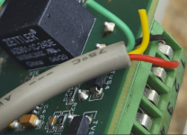
To verify my heater isn't the issue, I removed the 2-wire connection FROM the fireman switch/junction terminal TO the Jandy RS control box, and put in a JUMPER like this again (pic right below), so now the heater is ONLY controlled at it's own control panel and NOT by the Jandy RS control box (and iAquaLink):

jumper.JPG
And of course, my heater fires up as it's getting 24V again and sends it along to the pressure switch etc. So does this mean my Jandy RS control board is bad since only 6V is coming back out instead of 24V? Ugh.
 
Last edited:
99,

Your automation does not supply the 24 VAC, the heater does.

The 24 VAC, leaves the heater on one of the two fireman's control wires, goes into the automation and through a small relay. When this relay is open, then heater will not run, when the relay is closed, the voltage goes through the small relay and back to the heater's fireman's switch on the 2nd wire.

So..

Either the small heater relay is bad
The wires from the heater to the automation is cut or broken
The automation is not telling the relay to close.

Note.. The automation looks at the water temp and the set point temp that you set. If the water temp is less than the set point, the relay should be told to close. When the water temp gets to the set point or hotter, the relay is told to open.

The first step is to reconnect the wires to the fireman's switch and then short the two ends of the wire together inside your automation. If the heater runs, you know the problem is inside your automation system.

Thanks,

Jim R.
 
99,

Your automation does not supply the 24 VAC, the heater does.
@Jimrahbe

Correct, sorry if I wasn't clear about that. I just meant that the 24-28V is coming out of the heater here (red circle):
1688276989282.png

and then going INTO the automation control board here on PIN #2.
1688276428126.png

From that point it probably passes through a control relay, and when that relay is closed, I *SHOULD* be seeing 24-28V (instead of 6V) on PIN #1 (but I'm only seeing 6V). Since Pin #1 in the automation control board is only 6V, the heater is only receiving 6V back in this picture at point 3....

1688277160918.png

Leads me to believe the automation's control board causing the problem (like you said, maybe a bad relay that isn't closing properly, experiencing voltage loss due to bad contacts maybe or just a defective relay, etc.

So I'm also lead to believe that the problem has to be either a) the relay on the automation control board, or b) the wires between the heater and automation system.

My next step is to cut/re-strip those 2 wires between the heater and automation control board, reinsert those 2 wires into the connectors and try again. If that doesn't do it[, it seems like it HAS to be the automation's control board. Would you agree?

I do want to clarify what you said here, "The first step is to reconnect the wires to the fireman's switch and then short the two ends of the wire together inside your automation. If the heater runs, you know the problem is inside your automation system." because I've pretty much already done that by jumpering the wires as shown here in this picture below (that's how I was able to manually fire up the heater today -- I'm just shorting the wires, in the heater itself, instead of shorting them in the automation's control board. Logically its the same place, just a different physical place. So I kind of feel like I already did the first step? Correct?

1688276752425.png

Thanks @Jimrahbe !!
 

Attachments

  • 1688277091939.png
    1688277091939.png
    18.9 KB · Views: 1
Try skipping the fireman's switch and just control it via the 4-wire connection.
Just to be clear here, there is no 4-wire connection involved. There is only the two wire connection that goes from the heater to the Jandy automation control board. And I've already skipped the Jandy automation system by adding a jumper here inside the heater here, as shown in the pciture.

jumper-jpg.509330

That lets me turn my heater on and proves the heater itself is okay, but I have to run it manually with that jumper in place using the controls ON the heater itself, as opposed to controlling it from the automation system .

(SorryI responded to you guys in reverse order!)
 

Attachments

  • 1688277759341.png
    1688277759341.png
    18.2 KB · Views: 0
What I mean is I don't use the fireman's switch. I just use the 4 wire RS485 connection. The fireman's switch is not connected. The JXI supports this but not sure yours does.
 
Last edited:
What I mean is I don't use the fireman's switch. I just use the 4 wire RS485 connection. The fireman's switch is not connected. The JXI supports this but not sure yours does.
@PoolGate Yeah the Jandy Hi-e2 heater doesn't have a RS-485 connection with the 4 wires. I've attached the Jandy heater installation guide for your reference. (see page 14, section 2.10.4) and the troubleshooting guide. I don't have a fireman's switch either.
 

Attachments

  • Jandy Hi E2 Troubleshooting.pdf
    133.9 KB · Views: 2
  • Jnady Pro Series Hi-E2 R - Gas Heater.PDF
    2.9 MB · Views: 2
99,

Yep, the problem is with your automation..

I'd find the small relay that controls the heater and see if the contacts open and close as they should.

Jim R,
I'll look on the PCB board when its done raining out. My PCB # is "E0260500D" I imagine the controlling relay is one of those 5 black boxes? Is that a reasonable assumption?

1688306709949.png
 

Attachments

  • 1688306615710.png
    1688306615710.png
    244.6 KB · Views: 4

Enjoying this content?

Support TFP with a donation.

Give Support
So it doesn't look like I can find that 'exact' part # E0260500D easily when doing a Google search for buying a new control board (if I went that route). I might have to call Jandy support to find the part # that I could buy that board under or where to source it? I only found a couple new/used/not-used options (ebay, etc.) in a Google search.

I'm wondering the chance of actually replacing that stand alone relay. I'm not that great at circuit board repair (used to do lots of soldering/de-soldering in the past (25 years ago) but don't even have the equipment anymore) so wondering if I should just bite the bullet and buy a board (if they're even available anymore?) but like I said, can't seem to find that board anyways except 2 or 3 places online and I'm sure they're used...?

Any thoughts?
 
You have a complex system. Before doing anything, go into the settings and document all of the settings like aux port mappings and such. Also check eBay for used boards.
 
  • Like
Reactions: jesse-99
Very good point @Jimrahbe . If I can find a replacement relay and I wreck it, then so be it, I'd have a replacement board already and I'm not out anything except some time.

FWIW, I just came inside from working on the heater and main E0260500D board. In regards to the 2 wires (one red, one black), that go between the heater (at the fireman's switch, junction block) and the gray 10-pin connector (pins 1 and 2), I ended up cutting about 1" off each of the ends and re-stripping them and tightening them back down again. I got my voltmeter out again and turned on the heater (set temp above water temp) in the iAqualink app, and I could swear I heard a soft click (like the relay triggering closed). I watched voltage on pin #1 (which was always stuck at 6V), and this time the voltage kept jumping around 6V, 10, 8V, 16V, 6V, 20V, and after about 20 seconds landed on 28V and stayed there. Then I heard the heater fire up. Yay, but odd. I turned the heated off again through iAqualink, and voltage on Pin #1 went down to 5V roughly. Turned the heater on again through iAqualink and voltage on Pin #1 went right to 28V and heater turned on, again. I did this 3 more times and every time the voltage went to 28V right away and the heater fired up.

I wonder if a) my re-wiring and re-terminating the connections might have helped (since it's now working), and/or b) if the relay itself is maybe on its way out or "sticky". IIRC ,sometimes you can unstick a relay by giving it a bit of a whack/tap on it, though I didn't do that this time.

For reference, I did grab a picture of that relay that @Jimrahbe thinks it might be. Here it is: (I'll Google the part # and see if anything comes up)
1688331295271.png

Also, in that pic above and below, it looks like there might be a cold solder joint going to that relay and I'm pretty sure that's where Pin #1 of that 10 pin connector is too (which I just re-wired).

1688331583407.png

But since it's working for now, I think I'm going to leave it and press my luck... ?
 

Attachments

  • 1688331555535.png
    1688331555535.png
    520.7 KB · Views: 0
You have a complex system. Before doing anything, go into the settings and document all of the settings like aux port mappings and such. Also check eBay for used boards.
Yeah for sure definitely agree with that @PoolGate If I do end up replacing that board, I'm assuming I'll lose ALL of my settings that I've spent hours customizing and don't want to lose. I'm planning on calling Jandy tomorrow to find out if that board is replaceable as new or if it's been superceded by something else at this point? Looks like I might not need it (see post above) but, I want to be prepared regardless. I'm not looking forward to having to document all those settings, lol, but hmm, that might be a good idea to do whether I replace the board or not, just to keep the info here for reference in case the board dies or needs future replacing. All those AUX mapping settings, VSP settings, and tons more, losing all that would really suck.
 
Yeah for sure definitely agree with that @PoolGate If I do end up replacing that board, I'm assuming I'll lose ALL of my settings that I've spent hours customizing and don't want to lose. I'm planning on calling Jandy tomorrow to find out if that board is replaceable as new or if it's been superceded by something else at this point? Looks like I might not need it (see post above) but, I want to be prepared regardless. I'm not looking forward to having to document all those settings, lol, but hmm, that might be a good idea to do whether I replace the board or not, just to keep the info here for reference in case the board dies or needs future replacing. All those AUX mapping settings, VSP settings, and tons more, losing all that would really suck.
The daughter board is where all the settings are stored. So if you end up getting a new one, swap over that small board.
 
Thread Status
Hello , This thread has been inactive for over 60 days. New postings here are unlikely to be seen or responded to by other members. For better visibility, consider Starting A New Thread.