Jandy AquaPure Service Code 170

spencer25

New member
May 9, 2024
3
Hi,
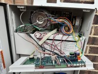
Today I started getting service code 170 and the pool pump isn't working anymore. Attaching pics of the wiring board.

Can someone please suggest what do I need to replace to resolve the error code 170? As per the manual, error code 170 indicates "Possible Front board service condition or unit not correctly wired to 120 VAC."

Searching through the forum, my understanding is that I need to replace the salt sensor but I don't know where that is! My salt cell isn't working so we have been using chlorine tablets for the past one year. Is there a way to not use salt cell system, and start the pool again?

Appreciate any help! Thank you!
IMG_9588.jpg
IMG_9587.jpg
 
Welcome to TFP
If you disconnect the PRIMARY wires coming from the salt cell transformer then the salt system has no power. You can also disconnect the RS485 wires from the RED connector as they control the salt cell on the AquaLink automation.
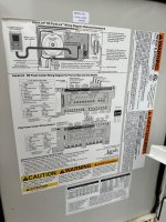
You would need to remove the lower panel to show the relays. The salt cell should be connected to the top left relay.
Now the pump is also connected to the top left relay. If the relay is working, the pump should work regardless if salt system is connected or not.
What type of pump do you have?
Show picture of automation with the circuit breakers and relays.
Are you OK working around electricity? You can power off the system before you remove the lower panel.
 
Thank you @HermanTX for your response. Adding a couple more photos for reference.

I powered off the system before removing the lower panel and took the picture.

Which PRIMARY wires shall I disconnect from the salt cell transformer? Also, are you referring to the RS485 RED connector on the bottom left side from the first photo that I attached?

Apologies. My DIY skills are limited so learning this for the first time!
 

Attachments

  • IMG_9593.png
    IMG_9593.png
    2.3 MB · Views: 8
  • IMG_9591.png
    IMG_9591.png
    1.7 MB · Views: 7
  • IMG_9595.png
    IMG_9595.png
    3 MB · Views: 7
I disconnected the salt cell from the top left relay, and now the pool is working again. The display now shows cell reversing as green light and Service as the orange light. Do I need to do anything to fix this?
Thanks to this forum! I am learning so many things on managing my pool.
 
I disconnected the salt cell from the top left relay, and now the pool is working again. The display now shows cell reversing as green light and Service as the orange light. Do I need to do anything to fix this?
Thanks to this forum! I am learning so many things on managing my pool.
Thanks for the photos. The top left relay (hard to see in your photo due to shade on the relays) should have 2 connections - the VS pump and the SWCG. You say you were able to remove the SWCG wires but then the lights should be out - not on. There is a wire coming from the SWCG transformer to the top left relay.
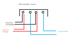
In the drawing below - Circuit Breaker provides power to the RELAY - it uses terminal 1 & 3 (on Jandy it is denoted as 2 & 4) but for sake of this discussion - they are 1 to 4 from left to right
Then the electrical cable from the pump also goes to terminal 1 & 3 because the VS pump needs constant power
The electrical cable from the SWCG transformer goes to terminal 2 & 4 because only when the relay is turned ON by automation then the SWCG gets power.
Jandy Filter Pump Relay with SWCG.png
So if you disconnect the SWCG (blue lines in my schematic) the SWCG should be completely off.

You have a multiplex board behind all the wires on the left side. It has multiple RED connectors on it. The lone RED connector on the main PCB has a single set (4 wires) that powers the Multiplex board (with multiple RED connectors). On the multiplex board there should be at least 3 wires (4 wires each) to the RED connectors - they should be one to the antenna, one to the VS pump and one to the SWCG. You will need to pull out all that extra wire wrapped in there and determine which is which. Use blue painter tape to mark them.

FYI - the booster pump should be connected to Relay Aux 1 which is the lower left Relay. That would have power From the circuit breaker to terminals 1 & 3 and power To the booster pump connected to terminals 2 & 4 (like the SWCG is connected on drawing above).
Lets stop here and answer any questions you may have.
 
Searching through the forum, my understanding is that I need to replace the salt sensor but I don't know where that is! My salt cell isn't working so we have been using chlorine tablets for the past one year. Is there a way to not use salt cell system, and start the pool again?
The salt sensor is the black threaded device with a wire leading from it that is facing down to the cement pad on the SWCG. With the pump off, that black ring can be rotated off and the complete sensor will come out. You can purchase a replacement sensor with wire. The wire runs to the SWCG board behind the main PCB.