IntelliCenter Quick Reference/Information Guide

I'm almost complete on a new pool build with an Intellicenter 521906 controlling everything (1 intelliflo pump, IC60, 2 Intellivalves, MasterTemp 400, water feature pump, lights...etc) Question about jumping relays to be able to control the IC60 independently...In your above example, you have 1 circuit breaker feeding your pump, IntelliChlor, and Heater all through the pump relay or am I missing something? Can the pump and the heater be on the same GFCI circuit breaker without causing any issues?

I believe my electrician has mine currently wired incorrectly (my intelliflo is wired through the load side of the pump relay) and I would like to do it the way you've described, I just want to make sure I understand correctly while I explain it to the electrician.

I've wired every panel the same way with the pump, heater and SWG on the same 20A GFi breaker and never had an issue. The Intelliflo should receive constant power. I use a jumpered relay to power the heater because I'm a big fan of heater bypasses and I don't want the heater to have power with no flow. For some reason 3 amps sticks out in my mind for the blower draw, the rest is low voltage and is very minimal.

I don't really see a reason to have the SWG on its own relay. If you don't want to run it for whatever reason, you could always add a feature circuit with a pump speed assigned to allow the pump to run but the Filter pump relay wouldn't activate.

I wouldn't consider myself attractive by any means....just something Tom Brady and Brad Pitt would conceive during a heated night of passion (which would certainly require more than 3 amps).
 
Last edited:
Brian.
I've wired every panel the same way with the pump, heater and SWG on the same 20A GFi breaker and never had an issue. The Intelliflo should receive constant power. I use a jumpered relay to power the heater because I'm a big fan of heater bypasses and I don't want the heater to have power with no flow. For some reason 3 amps sticks out in my mind for the blower draw, the rest is low voltage and is very minimal.
Thanks much and thanks for steering me in this direction quite some time ago. It has worked flawlessly... I love macros lol...

I don't really see a reason to have the SWG on its own relay. If you don't want to run it for whatever reason, you could always add a feature circuit with a pump speed assigned to allow the pump to run but the Filter pump relay wouldn't activate.
I agree. I just choose to do it this way for two reasons. 1. I have the relays to spare and so I can and 2. the way I have my schedules setup to take advantage of the winter/summer "time-of-use" plans from the power company, it made more sense to use macro's versus setting up the other way. This method just happens to work nicely for me but good point on the other method.

I wouldn't consider myself attractive by any means....just something Tom Brady and Brad Pitt would conceive during a heated night of passion
:laughblue: :laughblue:

Thanks again and be well...
r.
 
  • Haha
Reactions: bdavis466
Cool.. Just try to confirm the total amperage draw of the MasterTemp 400. I don't want to take a guess and then be wrong on that and I can't seem to find a reference anywhere. It can't be much though. The fuse for the fireman's switch is only 1.5 amps for gosh sakes. Like I said, mine is only 0.5 amps but it doesn't have all of the electronics that the MasterTemp has.

Let's ask @bdavis466 . He is the one who initially gave me the idea of jumpering the heater relay off of the load side of the pump relay and besides, he is a lot smarter than I am (notice, I didn't say more good looking though :poke: :p) . If he doesn't know what the amperage draw of the MasterTemp 400 gas heater is, he will surely know who does.

r.
Ron,

Don't know if this helps but I'll add it just in case. The Mastertemp design is similar to the Jandy Jxi. The only electrical draw is the 24 vac system which is protected with a 2 amp fuse for the Jandy Jxi or in the case of the Mastertemp 1.25 amps and the electric fan which is rated for .68 amps at 240 v and 1.4 amps at 120 v. But the only reference I could find was in the electrical installation section it says to wire to a 15 a breaker. In operation I measured operating load with a clamp on ammeter and measured about half these loads.

Hope this helps.

Chris
 
Last edited:
Ron,

Don't know if this helps but I'll add it just in case. The Mastertemp design is similar to the Jandy Jxi. The only electrical draw is the 24 vac system which is protected with a 2 amp fuse for the Jandy Jxi or in the case of the Mastertemp 1.25 amps and the electric fan which is rated for .68 amps at 240 v and 1.4 amps at 120 v. But the only reference I could find was in the electrical installation section it says to wire to a 15 a breaker. In operation I measured operating load with a clamp on ammeter and measured about half these loads.

Hope this helps.

Chris
Hi Chris. Thanks... Yes, I agree that it (MasterTemp) shouldn't draw more than a couple of amps at most. Since the IntelliFlo draws approx 14 amps max, if the OP uses a 20 amp breaker, I think he will be just fine.
Thanks again and stay safe and be well.
r.
 
Maybe I'm off in the weeds, but when in spa mode, will the SWG be running? An IC60 running the spa for a few hours would over chlorinate the spa, wouldn't it? This was my main reason for wanting to control the IC60 separately.
Werdnaycart
If you wire the IntelliChlor transformer directly to the load side of the pump power relay (which is what most folks do), then you have options in the Settings > Chemistry Control screen to set IF and how much the spa is chlorinated when in spa mode.
2020-06-08_6-35-43.jpg 2020-06-08_6-37-07.jpg

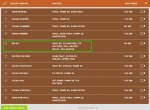
If you choose to wire the IntelliChlor transformer to it's own relay and jumper that relay off of the load side of the pump power relay, then you can control when the IntelliChlor is energized by the combo use of macros (Circuit Groups) and the schedules. Notice in the example below, that I use macros to determine when I want the IntelliChlor (and in my case, also the IntellipH), to be energized. The relay that controls power to the IntelliChlor transformer is named "Sanitation". My spa use macro is named "relax" (I found that I could not use "spa" as a naming convention for my Spa use, because it confused the Alexa skill (when that skill worked :mad:)) lol... Notice that some of my macros do not contain the circuit "sanitation" and others do.

2020-06-08_6-40-05.jpg

Hope this helps...
r.
 
Last edited:
  • Like
Reactions: Werdnaycart
Werdnaycart
If you wire the IntelliChlor transformer directly to the load side of the pump power relay (which is what most folks do), then you have options in the Settings > Chemistry Control screen to set if and how much the spa is chlorinated when in spa mode.
View attachment 145270 View attachment 145271

If you choose to wire the IntelliChlor transformer to it's own relay and jumper that relay off of the load side of the pump power relay, then you can control when the IntelliChlor is energized by the combo use of macros (Circuit Groups) and the schedules. Notice in the example below, that I use macros to determine when I want the IntelliChlor (and in my case, also the IntellipH), to be energized. The relay that controls power to the IntelliChlor transformer is named "Sanitation". My spa use macro is named "relax" (I found that I could not use "spa" as a naming convention for my Spa use, because it confused the Alexa skill (when that skill worked :mad:)) lol... Notice that some of my macros do not contain the circuit "sanitation" and others do.

View attachment 145272

Hope this helps...
r.


Thanks so much!
 
  • Like
Reactions: MyAZPool
That [SPD mounted as top breaker] might very well be true if one were to choose to mount the SPD upside down on the top of the Load Center (which I would highly NOT recommend since the top of the load center is adjacent to the low-voltage compartment or to the side (which again is NOT advisable on the left side of the Load Center).
But in my case, I choose to mount my SPD in the most logical location in my opinion (which was at the bottom of the Load Center), so the "closest" breaker is located in breaker slots 9/10.
Thanks for the explanation. I had misread the SPD advice I'd been given in a thread as first breaker instead of closest breaker to the knockout. You saved me from a faux pas. Thanks!
 

Enjoying this content?

Support TFP with a donation.

Give Support
Current and future IntelliCenter Users...

It appears that Pentair restructured some (but not all) of their online documents hyperlink hierarchy. I discovered that many of the links provided in the base documents of this thread were broken. Apologies, if you have experienced any "broken links" in this IntelliCenter Quick Reference/Information Guide. I've went through and fixed all of the links (hopefully), so they should be good now. If you find a broken link in the base posts of this thread, please let me know and I'll be happy to repair it.

In addition, through my travels within the Pentair IntelliCenter Pool Control System Portal this morning, I noticed that Pentair has removed much (but I still found a few that they must have missed), of the information and images that once referenced or advertised integration features such as the Apple WatchOS app, Google Assistant, Siri/HomePod, Google Home and Apple HomeKit. It appears that Pentair is now "pulling back" on some of these IntelliCenter integrations. Hmmm.....

Take care and stay safe...
r.
 
The power relay is designed to control either 240 Vac or 110 Vac equipment and devices.​
If the relay is used to control a 240 Vac device - The 1st and 3rd compression terminal screws (LINE SIDE) are used to connect each leg of the 240 Vac circuit to the associated circuit breaker.​
The 2nd and 4th compression terminal screws (LOAD SIDE) are used to connect each leg of the 240Vac circuit to the applicable line-voltage device (pump (see NOTE below), blower, etc.)​
If the relay is used to control a 120 Vac device - Then only the 1st compression terminal screw is used to connect the 120 Vac circuit (“black” power leg) to the applicable single-pole breaker.​
The 3rd compression terminal screw is used to connect the 120 Vac circuit (“black” power leg) to the applicable line-voltage device (light, low voltage lighting transformer, etc.). The “white” neutral leg is connected to the neutral bus bar.​

I’m in the process of wiring my intellicenter, and when I went to connect the 120v transformer for my intellibrite lights, the above confused me based on how I thought the relays worked.

When wiring a 120v load through a relay, wouldn’t you use the 1st compression terminal for the Line (120 Vac from the GFCI breaker) and the SECOND compression terminal for the load, such as the “black” leg going to the transformer (as opposed to connecting to the 3rd terminal, as stated)?

My understanding was that the relay connects (and disconnects) power running through pairs of terminals, with those pairs being terminals 1/2 and terminals 3/4. For example, when running 240 Vac through the relay, doesn’t 1 connect to 2 and 3 connect to 4 when the relay is activated? How would 1 connect to 3 with the relay active with 120 Vac?

Let me know what you think. Thanks!
 
  • Like
Reactions: MyAZPool
The 3rd compression terminal screw is used to connect the 120 Vac circuit (“black” power leg) to the applicable line-voltage device (light, low voltage lighting transformer, etc.). The “white” neutral leg is connected to the neutral bus bar.
Also, the white load neutral connects to the breaker neutral terminal and the white pigtail that comes with the breaker goes to the neutral bar.

This way, the neutral current goes through the breaker so that the gfci will work correctly.
 
I’m in the process of wiring my intellicenter, and when I went to connect the 120v transformer for my intellibrite lights, the above confused me based on how I thought the relays worked.

When wiring a 120v load through a relay, wouldn’t you use the 1st compression terminal for the Line (120 Vac from the GFCI breaker) and the SECOND compression terminal for the load, such as the “black” leg going to the transformer (as opposed to connecting to the 3rd terminal, as stated)?

My understanding was that the relay connects (and disconnects) power running through pairs of terminals, with those pairs being terminals 1/2 and terminals 3/4. For example, when running 240 Vac through the relay, doesn’t 1 connect to 2 and 3 connect to 4 when the relay is activated? How would 1 connect to 3 with the relay active with 120 Vac?

Let me know what you think. Thanks!
@1stchair
Yes Sir, you are absolutely correct.
Thanks for pointing out my error. I must of fell victim to copy/pasting and not correcting errors. ;)
The correct editing has been posted.
Thanks again...
r.
EDIT: @JamesW. I also added the additional instructions when using a GFCI breaker. Thanks. (y)
 
Last edited:
Thank you both for quickly confirming, and @JamesW for the detail on the white load neutral. That’s how I *thought* it should be, so your offering that detail reinforced it.

I still have some odds and ends to wrap up on the wiring front, but I’m almost ready to powering it up. Then the fun begins!
 
  • Like
Reactions: JamesW
If you find a broken link in the base posts of this thread, please let me know and I'll be happy to repair it.
@MyAZPool Thanks for what you have contributed here - I just found this thread and find it very useful.

FYI though, the Pentair links all seem to be broken again. Or at least they are not working from my PC. For example, I get a fail message similar to this one for every link:

Cannot serve request to /content/dam/extranet/product-related/product-manuals/pool-and-spa-equipment/intellifloxf-vsf/IntelliFlo_ProXF_VSF_Eng.pdf on this server


Apache Sling
@EngineerNerd
Thanks for the update.
Ya, Pentair is always changing things up on their website and every time they do, they break the hyperlinks.
I'll see if I can't work on em and fix the links.
Thanks again!
r.
 
  • Like
Reactions: EngineerNerd
Hi @MyAZPool. Your advice has been a blessing for me. I'm currently in the middle of an install with Dual Body personality card and I'm actually having to teach my PB about it based on your knowledge. Still trying to understand how to hook up my two intellichems (yes, I know. But I still want to give it a try, mostly for the pH side) and two intellichlors. But I digress.

So, I see the Alexa skill for the Intellicenter is currently not available. Do you know if Pentair have an ETA on that? Having the automation and not Alexa is frustrating.

Many thanks in advance!
 
This post is amazing and was exactly what I needed. So, first off, thank you for all this hard work and research.

I just went full-boat and upgraded from an old school intermatic timer and single speed pump to the intellicenter, VSF, SWG, ph dosing and a heat pump. This post helped me organize my install so much.

I installed over the weekend and turned it on Monday. I've figured out how to get it all running, and am working on schedules and groups. My only hiccup is despite all my efforts, the Intellicenter is failing to control the UltraTemp heat pump. It sees it, and the heartbeat shows it's connected on the pump side, but it won't kick on. The heat pump works manually just fine, just not through the RS-485 connection from the controller. Looks like this is not new, and EasyTouch and IntelliTouch had the same issues. I've changed the address to 2 on the intellicenter and the heater, in case there is conflict with the Pump on address 1. Still no love. Wondering if I should just use Relay mode instead. Thoughts?

The Intellichlor (linked through the Intelliph) also keeps sending alerts that it's lost connection, then immediately says it's back.

All that said, only 2 days in, and happy overall so far.
my intellichlor is also sending regular alerts that it has lost connection, and clearing those alerts within minutes. mine is wired to intellicenter as i dont have intelliph. did you ever resolve this? i am at a loss as to what's causing it...

@MyAZPool - HUGE thank you for taking the time to write this guide. real easy and clear.
 

Enjoying this content?

Support TFP with a donation.

Give Support
Thread Status
Hello , This thread has been inactive for over 60 days. New postings here are unlikely to be seen or responded to by other members. For better visibility, consider Starting A New Thread.