Hello!
I'm configuring an intellicenter for my new pool. I have a three way intellivalve w/ actuator, where the left output goes to the solar heating panels, (which loops back and Tees into the returns), and the right output bypasses the solar and goes straight to the returns.
I need a three-way valve because the solar system can only handle ~20gpm, so the idea is to leave the three way open to both when solar is enabled, and close the solar side when the temp is low.
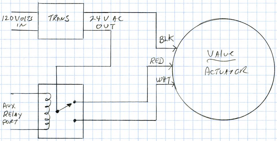
My question is that the intellicenter's 'Solar' connector only has two pins, while the intellivalve actuator has 3 pins, which surprised me. I can attach it to the 'Valve A' connector and get it working manually, but when it's independent like that it won't look at the 'solar' temp and activate, and while I could probably have the valve go on and off while the sun is up, I'd prefer it to properly hook to the special 'Solar' connector so it does it all automatically based on temp.
Is there some kind of 3->2 pin adaptor I should be using? Some other solution I haven't thought of? Why is are the Solar, heater and other connectors all 2-pin in the first place? I'd expect them to all be on intellivalves.
Thanks!
I'm configuring an intellicenter for my new pool. I have a three way intellivalve w/ actuator, where the left output goes to the solar heating panels, (which loops back and Tees into the returns), and the right output bypasses the solar and goes straight to the returns.
I need a three-way valve because the solar system can only handle ~20gpm, so the idea is to leave the three way open to both when solar is enabled, and close the solar side when the temp is low.
My question is that the intellicenter's 'Solar' connector only has two pins, while the intellivalve actuator has 3 pins, which surprised me. I can attach it to the 'Valve A' connector and get it working manually, but when it's independent like that it won't look at the 'solar' temp and activate, and while I could probably have the valve go on and off while the sun is up, I'd prefer it to properly hook to the special 'Solar' connector so it does it all automatically based on temp.
Is there some kind of 3->2 pin adaptor I should be using? Some other solution I haven't thought of? Why is are the Solar, heater and other connectors all 2-pin in the first place? I'd expect them to all be on intellivalves.
Thanks!