Last edited:
Hayward H400 - Bizzare Issue + IF code
- Thread starter BrianWithAY
- Start date
You are using an out of date browser. It may not display this or other websites correctly.
You should upgrade or use an alternative browser.
You should upgrade or use an alternative browser.
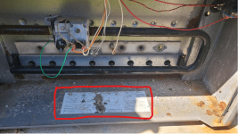
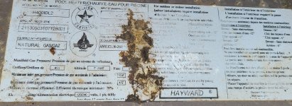
Yep. That's the oneI think it is the same heater I have H400IDL.
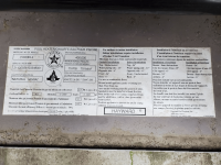
You have an H400IDL2.
Why is it in bypass operation?
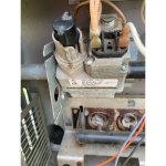
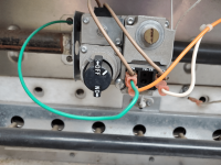
Why is the green ground wire on the gas valve?
The green wire will interfere with the voltage going to the valve.
Why is it in bypass operation?
Why is the green ground wire on the gas valve?
The green wire will interfere with the voltage going to the valve.
- May 3, 2007
- 16,964
- Pool Size
- 20000
- Surface
- Plaster
- Chlorine
- Salt Water Generator
- SWG Type
- Hayward Aqua Rite (T-15)
I actually have the H400IDL2 as well. If you have an external controller, the heater should be in bypass mode.
- May 3, 2007
- 16,964
- Pool Size
- 20000
- Surface
- Plaster
- Chlorine
- Salt Water Generator
- SWG Type
- Hayward Aqua Rite (T-15)
The heater is equipped for connection to an external 2-wire remote thermostat or a 3-wire remote switch.
A 2-wire thermostat has its own temperature sensor for regulating water temperature.
A 3-wire remote switch allows the “Pool” or “Spa” modes to be remotely selected.
Connect remote wiring to the terminal block on the Control Module.
For a 2-wire remote thermostat, connect one wire to the Pool terminal and the second wire to the 24 VAC terminal.
For a 3-wire remote, connect Pool/Low to the Pool terminal, Spa/High to the Spa terminal, and Common to the 24 VAC terminal.
Remote wiring should be run in a separate conduit. For runs less than 30 feet, use 22 AWG wire.
For runs over 30 feet, use 20 AWG wire.
Runs should not exceed 200 feet.
To configure the heater for 2-wire remote thermostat control, use the “Mode” key of the keypad to put the control in the “Standby” mode.
Then press and hold the “Down” and “Mode” keys for 3 seconds until the indication “bo” is shown on the display.
To operate the heater by remote thermostat, the heater’s control must be in either “Pool” or “Spa mode.
The heater’s display will show “bo”. The “Pool” or “Spa” LED will be illuminated.
The heater will fire when instructed by the remote thermostat.
The heater’s thermostat will function to limit the water temperature to a maximum of 104°F.
To operate the heater with a remote 3-wire switch, the heater’s control must be in the “Standby” mode.
The Standby LED will be illuminated.
When the remote switch is set to “Pool/Low”, the Pool LED will be energized and display will show the water temperature.
When the remote switch is set to “Spa/High”, the Spa LED will be energized and the display will show the water temperature.
The heater will use its internal thermostat to regulate the water temperature to the set point of the mode selected.
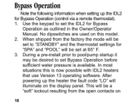
Bypass Operation
Note the following information when setting up the IDL2 for Bypass Operation (control via a remote thermostat).
1. Use the keypad to set the IDL2 for Bypass Operation as outlined in the Owner/Operator Manual.
No dipswitches are used on this model.
2. When shipped from the factory the mode will be set to “STANDBY” and the thermostat settings for “SPA” and “POOL” will be set at 65° F.
3. During a pre-install prior to pool/pump startup it may be desired to set Bypass Operation before sufficient water pressure is available.
In most situations this is now possible with IDL2 heaters that use Version 13 operating software.
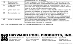
After powering up the heater the fault code “LO” will illuminate on the display panel.
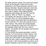
This will be a “soft” lockout resulting from the open contacts on the water pressure switch; the control will accept inputs via the keypad.
Follow the process described in the Owner/Operator manual to set Bypass Operation.
Bypass Operation cannot be set while any other fault code is displayed until that code is cleared.
After setting Bypass Operation (the display will read “bo”) set the heater to “SPA” or “POOL” as needed.
4. The display will continue to show “bo” for 10 seconds, then “LO” will be displayed again.
a. If the remote thermostat does not generate a call for heat the “LO” error will continue to be a “soft” lockout.
The control will accept keypad inputs to change the mode and it will remain in the selected mode when the error code is cleared.
The heater will not operate until the error code is cleared.
b. If the remote thermostat generates a call for heat the “LO” error will be a “hard” lockout.
The control will accept keypad inputs to change the mode and it will remain in the selected mode when the error code is cleared or the call for heat is removed.
It will not be possible to switch out of Bypass Operation until the error code is cleared
- May 3, 2007
- 16,964
- Pool Size
- 20000
- Surface
- Plaster
- Chlorine
- Salt Water Generator
- SWG Type
- Hayward Aqua Rite (T-15)
Ok, that seems odd to me.Yes, it does have a green wire:
Maybe it is a gas pressure issue.
Maybe it has more than one problem.
Hard to tell with really old units.
Maybe clogged burner tubes or a clogged heat exchanger.
Maybe the external controller is the issue?
Maybe the external controller is the issue?
- May 3, 2007
- 16,964
- Pool Size
- 20000
- Surface
- Plaster
- Chlorine
- Salt Water Generator
- SWG Type
- Hayward Aqua Rite (T-15)
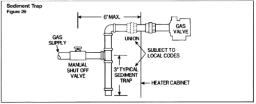
The odd part is that it fires with the nozzles tilted away from the burners but does not fire when the nozzles are in the correct position. This indicates something to do with the position of the black nozzle pipe which I thought might be due to sediment and why I asked about the sediment trap.
Maybe the gas valve is defective and it works when pointing up but not on its side?
The fan will pull the gas into the holes so the gas should still get into the combustion chamber if the door is on.
Even if the door is off, the holes are sucking in air and most of the gas should go into the combustion chamber and the burner tubes.
The fan will pull the gas into the holes so the gas should still get into the combustion chamber if the door is on.
Even if the door is off, the holes are sucking in air and most of the gas should go into the combustion chamber and the burner tubes.
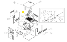
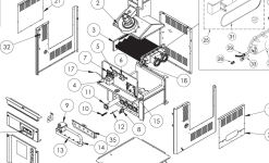
0 .
PART NO.
DESCRIPTION
1 IDXLJKT1250 TOP JACKET ASY - H250IDL
1. IDXLJKT1400 TOP JACKET ASY - H350/400IDL
2. IDXLBWR1930 COMBUSTION BLOWER
3. IDXLHXA1250 HEAT EXCHANGER ASY - H250IDL
3. IDXLHXA1400
HEAT EXCHANGER ASY - H350/400IDL
4.
IDXL2TRF1930
TRANSFORMER
5
IDXL2VPS1930
VENT PRESSURE SWITCH
6.
IDXL2BVS1930
BLOWER VACUUM SWITCH
7.
IDXL2FSB1930
FUSE BOARD
8.
HAXPSA1930
PRESSURE SWITCH ASY
9.
IDXLGSV0001
GAS VALVE NATURAL
9.
IDXLGSV0002
GAS VALVE PROPANE
10.
IDXL2IGN1930
SILICON NITRIDE IGNITOR
11.
IDXL2BRN1930
BURNER TUBE
12.
IDXLFLS1930
FLAME SENSOR
13.
IDXLBON1930
BURNER ORIFICE NATURAL GAS - H250/400IDPL2
13.
IDXLBOP1930
BURNER ORIFICE PROPANE - H250/400IDPL2
13.
IDXLBON1931
BURNER ORIFICE NATURAL GAS - H350IDPL2
13.
IDXLBOP1931
BURNER ORIFICE PROPANE - H3501DPL2
14.
HAXMAN1250
GAS MANIFOLD - H250
14.
HAXMAN1400
GAS MANIFOLD - H350/400
15.
IDXL2ICB1931
IGNITION BOARD ONLY
16A.
IDXL2PBA1250
PANEL/BEZEL/KEYPAD ASY - H250IDL2
16A.
IDXL2PBA1400
PANEL/BEZEL/KEYPAD ASY - H350IDL2, H400IDL2
16A.
IDXL2PBA1931
PANEL/BEZEL/KEYPAD ASY - CALIFORNIAN
16B.
IDXL2BKP1930
BEZEL AND KEYPAD ASY
16B.
IDXL2BKP1931
BEZEL AND KEYPAD ASY - CALIFORNIAN
16C.
IDXL2DB1930
DISPLAY BOARD ONLY
17.
IDXLWHM1930
WIRE HARNESS MAIN
18.
HAXWHA0006
WIRE HARNESS HI-LIMITS
19.
IDXLURA1930
UPPER RIGHT ACCESS COVER
20.
IDXLLRA1930
LOWER RIGHT ACCESS COVER
21.
IDXLLAC1930
LEFT ACCESS COVER
23.
HAXFCT1930
FLOW CONTROL THERMOSTAT
24.
CHXPLG1930
X” NPT BRASS PLUG
25.
HAXBPK1932
BY-PASS VALVE ASSY KIT
26.
HMXHLI2931
HIGH-LIMIT 135T
27.
HMXHLI2932
HIGH-LIMIT 160T
28.
CHXPSA1930
PRESSURE SWITCH ADAPTER
29.
CHXTBW1930
BULB WELL
30.
HAXFHD1931
FRONT HEADER ONLY
31.
HAXHOR1930
HEADER 0-RING
32.
IHXPHK1930
PLASTIC HARDWARE KIT
33.
IDXLTER1930
THERMISTOR
34
HAXCIA1930
CORNER PIECE KIT (4)
35.
IDXLAOK1250
AIR ORIFICE BRACKET - 250IDL
36.
IDXLAOK1400
AIR ORIFICE BRACKET - 400IDL
37.
IDXL2AOK1250
AIR ORIFICE BRACKET - 250IDL2
38.
IDXL2AOK1400
AIR ORIFICE BRACKET - 400IDL2
39.
IDXL2FSK1930
IDL2 FUSE/CONTROL BOARD FUSE SERVICE KIT (4) (NOT SHOWN)
40
What would you anticipate the cost to have a new one installed (Parts + Labor)?
I think I am tired of trying to keep this one alive.
I tore it completely down and cleaned it inside and out and now I get audible clicks but the fan won't kick on. I probably got water on something that I shouldn't have.
I think I am tired of trying to keep this one alive.
I tore it completely down and cleaned it inside and out and now I get audible clicks but the fan won't kick on. I probably got water on something that I shouldn't have.


