Hayward H250ed2c control board?

Sdhb

Active member
Jul 20, 2023
42
Canada
Pool Size
54509
Surface
Vinyl
Chlorine
Salt Water Generator
SWG Type
Hayward Aqua Rite (T-9)
Turning to TFP for help, thanks in advance.

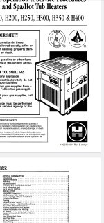
I have a Hayward H250ed2c natural gas heater (2 ish years old).

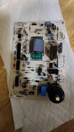
It was working, but now controls seem to be dead, but can confirm there is power getting to the unit, and some current coming out of the 24vac transformer out line (how much I'm not sure, but NC voltmeter is beeping on that wire so I assume there is power getting to control board..)

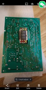
Looking at the control pcb board I think these contacts in the red circle might have come loose, as the main wire harness on the other side seems loose.

Any ideas to trouble shoot? My asumption is that even if something else is the problem, the control board should power up in some manner and give me a sign of such if there is power getting to it via the 24vac in contact?

If so, that leads me to believe the potentially interrupted circuit line on the board could be the issue.

Any ideas? Ty
 

Attachments

  • Screenshot_20230916_185124_Photos.jpg
    Screenshot_20230916_185124_Photos.jpg
    271.3 KB · Views: 10
  • 20230916_185028.jpg
    20230916_185028.jpg
    340.8 KB · Views: 9
  • Sad
Reactions: plnewb
There are 2 paths we can take.

1. If you're not handy with electronics or don't want to deal with troubleshooting, look on eBay etc for a spare board
2. If you're not handy with electronics, we can troubleshoot it using a cheap $20 oscilloscope and DMM and even build a replacement that you will be able to control over WiFi from inside the home

That board is so old tech that it should be relatively easy to troubleshoot - the biggest problem would likely be tracking down ICs that are obsolete
Thanks. Looks like this particular board only comes with the full assembly, and it's $595CAD new. Used not much less, so I'm hoping to repair it.

Wifi would be nice down the road, but initially I'm hoping just to get it functioning from the main controls first.
There are 2 paths we can take.

1. If you're not handy with electronics or don't want to deal with troubleshooting, look on eBay etc for a spare board
2. If you're not handy with electronics, we can troubleshoot it using a cheap $20 oscilloscope and DMM and even build a replacement that you will be able to control over WiFi from inside the home

That board is so old tech that it should be relatively easy to troubleshoot - the biggest problem would likely be tracking down ICs that are obsolete
Also I don't have an oscilloscope, but I do have a digital multimeter. Could we start with that?
 
Also I don't have an oscilloscope, but I do have a digital multimeter. Could we start with that?

Sure, but a cheap $20 oscilloscope would really save you $2000 in time, so buy one from Amazon so its there next week

The first thing you need to do is take clear, high res pictures of the ICs - we need to find out if these are custom parts or vanilla commodity parts
 
If so, did I miss the schematic for the "control board" that manages the whole system?

What you see is what we got from contributions of those before us who studied the circuitry.
 
Is your heater connected to any automation?

Any signs of rodents being in the heater?

See pages 13-22 - Universal H-Series Diagnostics Guide provides detailed diagnostics for troubleshooting problems and error codes.

No automation. Unfortunately no error codes to diagnose as it seems the entire control module is dead. No Sign of rodent damage.. All wires look good. But where the wire harness meets the PCB is loose. I think it needs to be re-soldered, maybe.
 
Last edited:
No automation. Unfortunately no error codes to diagnose as it seems the entire control module is dead. No Sign of rodent damage.. All wires look good. But where the wire harness meets the PCB is loose. I think it needs to be re-soldered, maybe.

Did you check all 13 steps in the diagnostic guide?
 

Enjoying this content?

Support TFP with a donation.

Give Support
Did you check all 13 steps in the diagnostic guide?
I tried but my control board is not pictured in the guide. It's quiet different.. Could there be a different guide for h250ed2c? My model code also dosen't correspond to the model code format on the cover of the diagnostic guide either.
 
Last edited:
Post pics of your heater.

How old is your heater?

See if the attached manual matches your heater.
 

Attachments

  • H Series Electronic Installation Guide.pdf
    1.5 MB · Views: 5
Looks like Allen may have given you the correct manual. The wiring diagram would be on page 16. System appears to be direct spark ignition. Circuit board is powered at the connection that you say seems to be loose. You can check voltage into the circuit board by removing the connector that you say is loose and checking voltage with a multimeter at the connections that correspond to the 'com' and "24V" on the connection to the circuit board. If you have 24V coming in on the wiring harness/connector, but the connection is indeed loose you may have a broken solder joint where the connector is joined to the circuit board traces. It may be that the broken solder joint is restricting the voltage to the board and the solder joints may need to be redone.
 
Post pics of your heater.

How old is your heater?

See if the attached manual matches your heater.
Yes that's the one, slightly different than the diagnostics manual you sent. I think there is a single integrated control board in mine vs multiple in the diagnostics manual. Will send a pic when I get home, but it's 100% the one shown below. Just over 2 years old, 1 year warranty of course..
Looks like Allen may have given you the correct manual. The wiring diagram would be on page 16. System appears to be direct spark ignition. Circuit board is powered at the connection that you say seems to be loose. You can check voltage into the circuit board by removing the connector that you say is loose and checking voltage with a multimeter at the connections that correspond to the 'com' and "24V" on the connection to the circuit board. If you have 24V coming in on the wiring harness/connector, but the connection is indeed loose you may have a broken solder joint where the connector is joined to the circuit board traces. It may be that the broken solder joint is restricting the voltage to the board and the solder joints may need to be redone.
TY.. I'm going to try soldering those joint or adding bypass wires. Stay tuned for an update!
 

Attachments

  • Screenshot_20230917_184548_Drive.jpg
    Screenshot_20230917_184548_Drive.jpg
    289.8 KB · Views: 4
Ok! Board is re soldered. Multiple breaks.. Can't believe how poorly constructed this is for something barely 2 years old...

So I have power to the PCB, I can hear the ignitor trying to light, but no ignition. I can also hear the (regulator?) turning the gas on just prior to the ignitor firing (and I can smell it so I know it's flowing). After 3 tries I get IF (ignition failure), and have shut off gas.

Any ideas on this one? I've cleaned out components that I can access without removing any other fittings so far. Ty
 
It would seem that the ignitor ( "direct spark ignitor" that lights off burners directly rather than a pilot, as opposed to a "hot surface ignitor" ) is not lighting off the burners directly. This can be due to dirt/corrosion of the ignitor assembly itself causing a weak spark or a problem with the flame pattern of the burners caused by dirt/corrosion of the burners or disruption of the gas/air mixture flow caused by blockages of the burner slots, inside of burner tubes or gas manifold orifices. Also possible but least likely is a problem with incorrect gas pressure. I would start with a thorough cleaning of the Ignitor assembly ( Amazon.com ) to include the spark rod/ flame sensor ( the part with the wire attached ), the flat surface attachment of the spark/sensor assembly to the ignitor bracket (both sides) and the attachment point of the ignitor bracket to the heater itself to insure that all these points have good bare metal to metal contact. Any further checking into a disruption of the gas/air mixture flow would require that you observe and follow all procedures regarding gas heater gas supply safety precautions. Cleaning of the parts on the ignitor assembly/ignitor bracket should be done with a small "hobby" type file (metal or diamond) or steel wool rather than sandpaper.
 
It would seem that the ignitor ( "direct spark ignitor" that lights off burners directly rather than a pilot, as opposed to a "hot surface ignitor" ) is not lighting off the burners directly. This can be due to dirt/corrosion of the ignitor assembly itself causing a weak spark or a problem with the flame pattern of the burners caused by dirt/corrosion of the burners or disruption of the gas/air mixture flow caused by blockages of the burner slots, inside of burner tubes or gas manifold orifices. Also possible but least likely is a problem with incorrect gas pressure. I would start with a thorough cleaning of the Ignitor assembly ( Amazon.com ) to include the spark rod/ flame sensor ( the part with the wire attached ), the flat surface attachment of the spark/sensor assembly to the ignitor bracket (both sides) and the attachment point of the ignitor bracket to the heater itself to insure that all these points have good bare metal to metal contact. Any further checking into a disruption of the gas/air mixture flow would require that you observe and follow all procedures regarding gas heater gas supply safety precautions. Cleaning of the parts on the ignitor assembly/ignitor bracket should be done with a small "hobby" type file (metal or diamond) or steel wool rather than sandpaper.
Thanks. I removed the entire ignitor assembly and used steel wool on the two prongs. Reinstalled and tried it again and still no ignition, though I can hear it trying as before. I guess now I need to check for blockages of gas in orifices?
 

Enjoying this content?

Support TFP with a donation.

Give Support
Thread Status
Hello , This thread has been inactive for over 60 days. New postings here are unlikely to be seen or responded to by other members. For better visibility, consider Starting A New Thread.