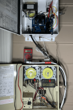
Hayward Chlorine Generator Display Not Working

ToanDang

Member
Apr 16, 2024
9
Atlanta, GA
Hi,
I am having the same issue describe here on this thread Hayward Aqua Rite transformer bad?.
I do have 120V going to A-1 and 120V going into A-4. I don't understand where I can measure 240V. Measuring across A-1 and A-4 giving me nothing. I don't have any voltage across the two yellow cable.
Would the solution be as simple as replacing the timer switch which have the two 120V lines going into the Hayward GLX-PCB-RITE?

Please help. Thank you in advance.
 
T,

The most likely reason that you got zero volts when you measure between A1 and A4 is that you have lost one of the two phases (L1 and L2) that make 240 volts..

When a transformer is wired for 240 Volts AC.. if it got the same 120 volts on each leg, there would be no difference between them or zero volts.. But, in real life, there are two difference 120 volts AC sources called L1 and L2.. They are 180 degrees out of phase, so the voltage difference between them is 240 volts.

You need to disconnect the AC power going into the transformer and then measure the two input wires and see what voltage you get. Most likely one of the wires will have 120 volts to ground and the other will have zero.. You cannot run this test with the transformer in the circuit.

Then follow the wiring back to the source and see where you have lost the phase.

Thanks,

Jim R.
 
T,

Tell me what voltage you get when you test between pin 1 and 3 on the timer on the left.

Just to be sure.. The connection on the far left is gnd, then pin 1, 2, 3 and 4..

Thanks,

Jim R.
 
Hi Jim,
It got late last night to mess around with electricity.
I got 0v between pin 1 and 3 on the timer. Pin 1 to ground is around ~120v and Pin 3 to ground is ~120v, but not between them. The same result on the black and while lines coming in from the ground. If I understand you correctly, these two lines should be "180 degree out of phase", making up 240V difference.
Could this be the case somewhere not ground correctly?
 
T,

It has nothing to do with any ground..

Let's start at the beginning..

Coming into your main house circuit breaker panel you have two 120 volt wires that are out of phase by 180 degrees. They are called L1 and L2.

If you want to run something off of 240 Volts AC, you must use L1 and L2. You can't use two L1s or two L2s.

So.. either your whole house does not have 240 Volts, which I really doubt, or somewhere between where L1 and L2 enter your house and your pool equipment, you have lost one of them, or you wired your timer with two L1s or two L2s.

Step one to troubleshoot.... Find the 240 Volt house breaker that feeds your pool equipment. Measure between the two output of that breaker. Do you have 240 or not?? If you have 240 volts, then move on down to where the AC power comes into your pool equipment and check there. If you do not have 240 out of the main panel breaker that feeds your pool equipment, then most likely the breaker is bad.

Thanks

Jim R.
 
I look at the breaker box. I have a double breaker for the pool with a red and a black lines. Measuring the voltage betwen the two, I got 240V. Since, I am seeing the 240V lines are black/red but going into the pool switch as black/white. There must be something else in between.
I bought this house last May and still figuring things out.
 
T,

You are on the right track..

Does the breaker in the house panel feed a breaker at the equipment pad?

And you are correct.. If a red and black leave the breaker, where do the go?? That would be the first thing to find.

Thanks,

Jim R.
 
I think my problem is over the winter I took out the old SR Smith fiber optic pool light. That light power line must have run through the pump timer switch. I pool was closed over back then so I did not notice the problem. Now, I got to figure out how the wiring was done.
 

Enjoying this content?

Support TFP with a donation.

Give Support
T,

In post #8 you said the wires from the pool circuit breaker were Red and Black. Now you say they are Blue and Blue. :scratch:

In any case, if the wires change color, there should be some kind electrical box where that happens..

Also.. it is very very unlikely that 240 volts was used for any kind of pool lighting..

Sorry, but some one on your end is going to have to figure this out. :(

Jim R.
 
@Jim,
I was able to trace the wires back to the old pool light and found one 120V line was not connected. Reconnect that, measured 240V going into the pool timer L1 & L3, put all the original part back together, and everything now comes up as expected.
Next is getting the pool ready with adding salt and inspect the cell as indicated by the chlorinator.
Thank you for your help walking through everything.

T
 
T,

Glad you were able to figure it out... :goodjob:

I hope if you learned anything here, it is that you can not reliably test 240 volts by testing each leg to ground. You must test between the two hot wires.

Thanks,

Jim R.