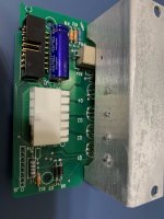
For the last month or so my Jandy/Aquapure Unit started with error code 123. It is 5+ years old. After cleaning of the salt cell with acid, still no free chlorine being produced so I began to use chlorine tabs. Finally ordered the new round PLC1400 kit and had it installed. Still receiving the error code 123 and getting frustrated. Does that mean I have to replace a circuit board or the whole darn control panel? On my goggle searches I could not even found the back circuit board for sale. Any suggestions?
AquaPure 1400 receiving error code 123
- Thread starter mariuscd
- Start date
You are using an out of date browser. It may not display this or other websites correctly.
You should upgrade or use an alternative browser.
You should upgrade or use an alternative browser.
- Jul 21, 2013
- 52,882
- Pool Size
- 35000
- Surface
- Plaster
- Chlorine
- Salt Water Generator
- SWG Type
- Pentair Intellichlor IC-60
Welcome to TFP.
Did you replace the cord with the cell?
 www.troublefreepool.com
Also look inside the cell at the cord end. The three pins go inside and connect to the plates. If one of them is rotted away, it's time for a new cell and cord.
Otherwise the back circuit board may need replacement.
Did you replace the cord with the cell?
Jandy AquaPure SWG - Further Reading
Error 123
That error is low or no current to the cell. First thing to check is the cord. Look for heavy corrosion at both ends. You can sometimes fix it by cleaning off the corrosion.Also look inside the cell at the cord end. The three pins go inside and connect to the plates. If one of them is rotted away, it's time for a new cell and cord.
Otherwise the back circuit board may need replacement.
Yes, I use the new cord from the kit, pretty much I used all the kit, so everything is new on that side.
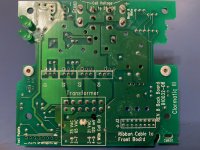
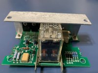
I cannot find a place to buy the back circuit board. By the way there are 2 boards there, one is smaller that has the cell power connected to it, and one bigger that has the sensor connected to oy.
I cannot find a place to buy the back circuit board. By the way there are 2 boards there, one is smaller that has the cell power connected to it, and one bigger that has the sensor connected to oy.
- May 23, 2015
- 24,446
- Pool Size
- 16000
- Surface
- Plaster
- Chlorine
- Salt Water Generator
- SWG Type
- Pentair Intellichlor IC-60
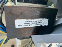
Transformers rarely go bad. They are very robust. More than likely the board is bad and that connector needs to be replaced.
Components like connectors and pins can be found on DigiKey or Mouser Electronics.
Post a picture of the boards. Get close up and really look closely at them. There may be components on the board that look fried or traces on the board that look charred.
Components like connectors and pins can be found on DigiKey or Mouser Electronics.
Post a picture of the boards. Get close up and really look closely at them. There may be components on the board that look fried or traces on the board that look charred.
- May 23, 2015
- 24,446
- Pool Size
- 16000
- Surface
- Plaster
- Chlorine
- Salt Water Generator
- SWG Type
- Pentair Intellichlor IC-60
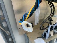
You can see where that connector got fried. That is the heart of the problem in terms of it being a bad design. Those two yellow wires come from the secondary side of the transformer which is lower voltage and higher current. Joule heating (electrical heating) is a function of current and they are trying to cram 6A of current in through that little plastic connector. Its a bad design but not something you can easily fix unless you feel comfortable doing board-level electrical work (the fix is to make the connection using a larger gauge wire to lower the resistance). It's basically those two pins supplying the power for the cell to generate chlorine while the other secondary winding on the transformer (19V @ 1A) is supplying the low power for all the electronics. They should have put the higher power wires on a totally separate connector to handle the greater heat load but, as is typical with large corporations, making it cheaply is the primary concern.
The transformer is fine ... I would be hugely surprised if it were damaged in any way. Transformers are nearly impossible to damage electrically and all it's doing is supplying power to the board. It's the board connector design that is the problem.
You've got choices though. If you feel comfortable doing the solder/de-solder work, that connector on the board and it's mating connector on the transformer can be replaced. It'll take a little bit of patient electrical work, but it's entirely doable. You'll pay more in shipping for the connector and new pins than the actual parts themselves. But, if your not able to do the electrical work, then you'd have to replace the board. Unfortunately, you still need to rewire a new connector onto the transformer wires, but again, it's really not that hard to do.
@ogdento might be able to offer some of his wisdom. As well, @Dirk has done some similar work on his Pentair IntelliPH / IntellChlor setup that has a knwon issue with weak connectors blowing out expensive boards.
Thank you. To rewire a new connector onto the transformer wires, is that clamp style?
If you can buy the parts and then find a local repair shop to the work sounds like a good plan to me.
- Dec 13, 2020
- 752
- Pool Size
- 19600
- Surface
- Plaster
- Chlorine
- Salt Water Generator
- SWG Type
- Jandy Aquapure 1400
I would consider cutting the wires to the burned pins, soldering new 16 gauge wires to the board, and joining things back up with serious bullet connectors. This is assuming the low current pins are still okay.
- Nov 12, 2017
- 11,887
- Pool Size
- 12300
- Surface
- Plaster
- Chlorine
- Salt Water Generator
- SWG Type
- Pentair Intellichlor IC-40
In my scenario, there was nothing wrong with the board or the power supply, only the connector itself. The pins are cheap, they lost contact, probably because they started corroding, which added resistance which then caused excessive heat, which then fried the connection and the surrounding plastic connector. I didn't bother replacing the whole connector, which IMO would only start the process over again! Instead, I cut off the connector, both halves, and soldered the wires directly to the board. it wasn't easy, but easier than locating and replacing the two connector halves would have been (half the work)!
Similar to what @generessler is suggesting, but without the extra set of connectors he's talking about. I don't see the need for those.
This means I can no longer easily disconnect the board, but so what. It works and the issues of the weak-link connector are eliminated permanently. If I ever have to replace the board, I'll cut the wires and solder them onto the new one. If you want to try this, I'll dig up my write-up about how I did it.
I am having a hard time finding the right connector, the female one that is connected to the transformer I thought is the "https://www.digikey.com/en/products...61388?s=N4IgTCBcDaIOoFkDMB2ADAVgLQDkAiIAugL5A" , which almost looks like it will fit, spacing seems correct, but does not plug in. I think soldering the wires just for the burned connector maybe the easiest solution. The remaining not burned connectors can stay in place since they are not stressed by high amperage. Thank you for the soldering suggestion.
Looking closer to the board connection of the 2 burned pins, they are going to one island only, so it seems that they try to mitigate the high amperage this way, using 2 pins. I hope I am right since I will be soldering the 2 wires together on that common island. Also the spacing between the soldered pins is rather small, so it will be a challenge.
- Dec 13, 2020
- 752
- Pool Size
- 19600
- Surface
- Plaster
- Chlorine
- Salt Water Generator
- SWG Type
- Jandy Aquapure 1400
@JoyfulNoise was right. A standard Molex pin, which these look like, is good for 5 amps. The cell draws up to 8. So two pins have only 2 amps excess capacity. Outdoors in all atmospheric conditions for maybe decades, that's extremely marginal. That's why I suggested more robust connectors. A good quality standard push-on spade or bullet connector as I listed is good for 30 amps and intended for harsh conditions like engine compartments. You can easily make them more weatherproof with heat shrink tubing. If they do arc, they don't burn up the board.
Last edited:
- Nov 12, 2017
- 11,887
- Pool Size
- 12300
- Surface
- Plaster
- Chlorine
- Salt Water Generator
- SWG Type
- Pentair Intellichlor IC-40
And there's the rub. When one of the pin sets loses its conductivity (to cheap metal or poor tinning, or corrosion, or whatever) it stops carrying its share of the current, foisting it on to the other pin set, which can't handle it. This is a case of the engineering spec looking OK "on paper" and the cost looking OK to the bean counters, but then reality sets in, which doesn't care about either!Looking closer to the board connection of the 2 burned pins, they are going to one island only, so it seems that they try to mitigate the high amperage this way, using 2 pins. I hope I am right since I will be soldering the 2 wires together on that common island. Also the spacing between the soldered pins is rather small, so it will be a challenge.
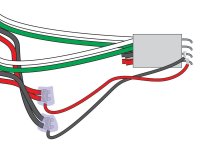
If you're sure two pins are the same connection, then don't try to join two fat wires onto the same circuit board trace. Join them off the board with a third wire of suitable gauge (I'd solder them), and then run that single wire to the board. That'll accomplish two things: the majority of the current will be flowing through the off-board connection, not through a circuit board trace, and you'll have a lot easier time of soldering to the board. If it's like the board I fixed, that third wire would carry next to nothing, only what the little components on the board might be using. The power-sucker, which is the SWG, will get its current through the off-board connection. If that's true of your board, that third wire can be much smaller, making the connection to the board that much easier. I have a drawing that illustrates that for my particular board. It's likely the same would apply to yours.
They do it the way they do it (using cheap connectors) in part to make the board more easily replaceable, but primarily to facilitate initial assembly and shave labor costs. You don't have that concern, so can afford the time to make a better connection. Again, @generessler's suggestion to use connectors off the board is fine, but not more current-capable or corrosion-proof than soldering. Those bullet connectors are great, and time-proven in harsh conditions, but two of them utilize six mechanical connections, soldering eliminates all six of 'em. It was mechanical connections that got you here.
If the following could apply to your board, you can make the repair quite easily, without removing/replacing the original connector and with minimal impact soldering onto the board. In my case, the big fat red and black wires power my SWG, the little black and red wires power the circuit board (so can be much smaller). The original green and white wires, which also carry little current, could be left as is. Now all the SWG's current flows through that splice, not the connector, and not the circuit board traces.
- Nov 12, 2017
- 11,887
- Pool Size
- 12300
- Surface
- Plaster
- Chlorine
- Salt Water Generator
- SWG Type
- Pentair Intellichlor IC-40
The pins on my board's connector are much easier to get at. Yours are more encased into the connector, and the bottom row might not be accessible at all from above. If you can get away with this smaller single-wire idea, then maybe you can solder it/them to the traces on the other side of the board. You can see my connector lends itself more to the fix I described above.
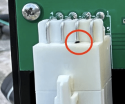

Thank you everybody for the help. I went on with soldering the 2 wires directly to the board, and it seems that did the trick, no more 123 error.
In conclusion if somebody has this error, first check the cable to the cell, make sure no corrosion or other issues there, if necessary fix that and check again for the error.
If the error is still there, check if the board connectors are burned. If that is the case, take a picture of board and using zoom take a close look. There may be components on the board that look fried or traces on the board that look charred, that means you have to get a new board (Amazon). If board seems OK or you got a new board, apply one of the fixes suggested above for the burned connectors.
Lastly if the salt cell was not cleaned recently do that too. Hopefully after all this the 123 error should go away, if not, then probably you need a new salt cell.
- May 23, 2015
- 24,446
- Pool Size
- 16000
- Surface
- Plaster
- Chlorine
- Salt Water Generator
- SWG Type
- Pentair Intellichlor IC-60
I would suggest seasonally checking the board, cables and connectors BEFORE waiting to get the error code. Often times you can spot corrosion or pin damage on the connectors before it becomes catastrophic. Chips and components blow up because the corrosion/damage has gotten to a point where voltages and currents cannot be maintained at proper spec and that usually leads to runaway electrical problems. A good circuit designer uses pSpice and other circuit analysis tools to model their designs when they go out of spec but not every problem can be designed away. Sometimes it comes down to “preventative maintenance is the best solution”.
- Nov 12, 2017
- 11,887
- Pool Size
- 12300
- Surface
- Plaster
- Chlorine
- Salt Water Generator
- SWG Type
- Pentair Intellichlor IC-40
Glad you got it fixed! Awesome.Lastly if the salt cell was not cleaned recently do that too.
Just want to add: I think it was @JoyfulNoise that taught us not to clean a salt cell just as a troubleshooting step, but rather only if it really needs it. Gently spraying those plates with water to free up loose calcium is fine, but acid bathing them does shorten their life to some extent (depending on how aggressive the acid solution). Keep your CSI in check (slightly negative, like between -0.3 to 0.0) and use as little acid on the plates, as seldom, as possible.
Thread Status
Hello , This thread has been inactive for over 60 days. New postings here are unlikely to be seen or responded to by other members. For better visibility, consider Starting A New Thread.


