10 Day Old IC-40 Just Went Dark

Here’s a real life question. Got a mother in law in distress that needs our daily help plus more work than usual across everything else. I don’t have near the time bandwidth as usual.

Do you guys have any idea whether, if I took the easy way out and replaced my 12 year old IntellipH, that would be more likely than not to give me at least a couple of years service?
 
… if I took the easy way out and replaced my 12 year old IntellipH, that would be more likely than not to give me at least a couple of years service?
And probs more importantly, whether doing that is at least a likely short term fix? On my own I can’t see the other hobgoblins that might possibly be causing this set of issues. Big thanks.
 
That’s exactly how mine began, although yours looks like more corrosion than charring. Usually the intelliph fails as a result of the connection issue. I would run your new SWG bypassing the intelliph for a couple of days. If it performs normally, then you know the issue is the IPh..Then Prepare to clean the connectors really well and employ the fix.
Looks like one of the pins (connected to one of the black wires) is going. Apply the red-red, black-black fix (if the IpH is no longer under warranty). You can mess with the pins if you like. I wouldn't. I'd bypass them, using this option of the fix, then it doesn't matter if the pins are connecting or not, or if they continue to degrade or not. You won't be able to easily disconnect the board from the cabling any longer, but, you know, so what.
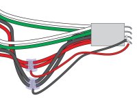
IntellipH-Mod-3.jpg

I doubt you need a new IntellipH, unless money is no object. Try this first. You would need some soldering skills. You don't need to solder the connections shown on the left, you could do all that with a couple of wire nuts or Wago connectors. But you'll have to solder the two smaller wires to the pins, as shown on the right.

As far as voltage measurements….without a “load” you may have correct voltage. However when you need voltage across a terminal that can’t support the amperage needed or have resistance you would experience a voltage drop.
+1, this is exactly what I was going to suggest.

I don't think we've ever seen an IpH destroy an IC. I think it more likely you had two problems happening at the same time (just bad luck): a bad IC and a bad pin in your IpH. Or the first IC was bad, and the pin of IpH only failed after the new IC was installed, or some mutation of those scenarios. But two problems that both need(ed) solving. You've solved one (the new IC), you just now need to solve the other. For now at least, you don't need to sleuth what went down when, you just need to fix what you know is broken (the burned/corroded pin). If that doesn't get you running, then you can start sleuthing again.

And again, I wouldn't waste time trying to restore the pins themselves, they're telling you they are bad, and even if you got them working again, another failure of those pins, or a different set of pins, is just waiting in the wings. The little jumper wires solve for that permanently.
 
Last edited:
Looks like one of the pins (connected to one of the black wires) is going. Apply the red-red, black-black fix (if the IpH is no longer under warranty). You can mess with the pins if you like. I wouldn't. I'd bypass them, using this option of the fix, then it doesn't matter if the pins are connecting or not, or if they continue to degrade or not
The diagram helps a bunch, thanks Dirk -- I had read Lake Placid's thread a few days ago (but pretty quickly, since my pins looked good) and understood the general idea that it was a splice - jump fix, slightly different than the approach you used in your original fix, but I didn't mine down to full understanding at that point since it did not appear to be my current problem. Now I think I get it the complete concept.

Lake Placid, one of the things that jumped out even on the fast, first read was how cleanly you had executed the fix. Really nice work. At the end of the day, mine won't have to look quite that showroom perfect, I just have to make sure everything is electrically tight and insulated. My biggest challenge is probably to make sure that during the soldering work, I keep the soldered pins/wires totally isolated from each other, with no stray solder making a short possible.

I doubt you need a new IntellipH, unless money is no object. Try this first. You would need some soldering skills. You don't need to solder the connections shown on the left, you could do all that with a couple of wire nuts or Wago connectors. But you'll have to solder the two smaller wires to the pins, as shown on the right.
Money is an object of course but time is too. This IpH fix will mean buying a soldering iron and solder (it's been years) and then practicing before attempting the fix. On the other hand, I can get that tool and solder more quickly than I can buy an IntellipH at a "less than peak retail" price. So I guess even time is on the side of the fix.

As far as voltage measurements….without a “load” you may have correct voltage. However when you need voltage across a terminal that can’t support the amperage needed or have resistance you would experience a voltage drop. Ohms law…..voltage, amperage, and resistance all play a part.

+1, this is exactly what I was going to suggest.

I don't think we've ever seen an IpH destroy an IC. I think it more likely you had two problems happening at the same time (just bad luck): a bad IC and a bad pin in your IpH. Or the first IC was bad, and the pin of IpH only failed after the new IC was installed, or some mutation of those scenarios. But two problems that both need(ed) solving. You've solved one (the new IC), you just now need to solve the other ...
Super helpful. Two problems happening at the same was on my list, I just didn't want to assume that possibility and miss another root cause that might explain everything. Given Ohm's Law (and all the other laws @JamesW shared, thanks for those ... I think 😆), I guess the "apparent good voltage testing" I did up in the automation previously, to test the power supply / transformer output, could potentially have left undiscovered an underlying voltage output problem up there. Per Ohm's, isn't that necessarily true? But in addition, the continued proper function of the new IC when connected directly to the IntelliTouch over time starts to rule that out, especially in light of the known failure mode of the IntellipH that you guys have so generously educated me about.
 
... Try this first. You would need some soldering skills. You don't need to solder the connections shown on the left, you could do all that with a couple of wire nuts or Wago connectors. But you'll have to solder the two smaller wires to the pins, as shown on the right.
Here's a newbie question -- any advice on the type of solder and/or soldering iron to buy or does that really not matter much? Just googled types of solder and it's quite a list. 1. Lead-Based Solder · 2. Lead-Free Solder · 3. Rosin-Core Solder · 4. Acid-Core Solder · 5. Flux-Core Solder · 6. Solid-Core Solder · 7. Silver-Alloy Solder · 8. Lead-Alloy Solder.

I only remember there being one. 🙃
 
I guess the "apparent good voltage testing" I did up in the automation previously, to test the power supply / transformer output, could potentially have left undiscovered an underlying voltage output problem up there. Per Ohm's, isn't that necessarily true?
The testing you did would not have included the IPH connectors AND the resistance they would induce into the circuit - which would have an effect on the voltage.
 
  • Like
Reactions: Dirk
Here's a newbie question -- any advice on the type of solder and/or soldering iron to buy or does that really not matter much? Just googled types of solder and it's quite a list. 1. Lead-Based Solder · 2. Lead-Free Solder · 3. Rosin-Core Solder · 4. Acid-Core Solder · 5. Flux-Core Solder · 6. Solid-Core Solder · 7. Silver-Alloy Solder · 8. Lead-Alloy Solder.

I only remember there being one. 🙃
I use an old RadioShack adjustable wattage soldering iron. It will output from 0 to 50 watts. I can fine tune the heat I need for the wire I'm soldering. It also has replaceable tips. I'd suggest using the smallest tip you can as the area of connector leads is kind of tight. I use Rosin Core solder. It comes in varying thicknesses. Get a finer thickness like .032 diameter. It will melt and flow easier for the tight space. If you want a pic of my old soldering iron lemme know.
 
  • Like
Reactions: Dirk and Brushman
I use an old RadioShack adjustable wattage soldering iron. It will output from 0 to 50 watts. I can fine tune the heat I need for the wire I'm soldering. It also has replaceable tips. I'd suggest using the smallest tip you can as the area of connector leads is kind of tight. I use Rosin Core solder. It comes in varying thicknesses. Get a finer thickness like .032 diameter. It will melt and flow easier for the tight space. If you want a pic of my old soldering iron lemme know.
Really helpful. The best part is, I'm pretty sure my old soldering iron was a RadioShack product. Lots of the stuff I used to solder was from RadioShack.
 
Rosin core. Low wattage iron. What's critical is that you work quickly, with as low a wattage as will melt solder. What you don't want to do is heat the pin up enough to desolder it from the board. That's the mistake I made, and the fix for that was considerably more complicated.

Wrap the wire tightly around the pin, as far away from the board as possible. Tin the iron tip (clean it well, then melt solder onto the tip to coat the tip). Touch the tip to the wire, but not the pin. Touch the solder to the tip and the wire simultaneously, and let the flowing solder heat the pin (not the tip). As soon as you see the solder take to the pin, pull the tip off.

If you get it wrong, don't continue to apply heat. Let it all cool, like, cool to the touch, then start again. Don't let the intersection of the pin and the board get too hot.
 
Last edited:
  • Like
Reactions: Brushman

Enjoying this content?

Support TFP with a donation.

Give Support
Lake Placid's work was really great, both functionally and visually. I've done careful splicing and heat shrink work a bunch, but typically I only do that there is a visual aspect that I'm going for, like in home audio and video, where those connections are visible. In this little IpH box, I obviously don't care about that part, so I am wondering whether there is a performance downside to simply using wire nuts or liquid electrical insulation (tight and carefully of course) to create the splice/jump connections.
 
I can heat shrink but in that confined space it would probably add to the degree of difficulty at least for me.
 
Lake Placid's work was really great, both functionally and visually. I've done careful splicing and heat shrink work a bunch, but typically I only do that there is a visual aspect that I'm going for, like in home audio and video, where those connections are visible. In this little IpH box, I obviously don't care about that part, so I am wondering whether there is a performance downside to simply using wire nuts or liquid electrical insulation (tight and carefully of course) to create the splice/jump connections.
See recent post.
 
My original "vision" was to not cut the reds and blacks. Just strip them, bind them together with one end of the jumper, solder all that together, then coat the connection with some sort of insulating compound (epoxy, silicon caulk, etc).

Functionally, realistically, a Wago connector would take 1/50th of the time and work just as well. I just like to make things difficult.

So no, no real difference between heat shrink and any other reasonable way to insulate. They used to use electrical tape "back in the day," and if done correctly would also last forever.
 
  • Like
Reactions: Brushman
Thoughts on splice wire gauge, is 16 awg about right?
Shoot, I don't have any wire in front of me just now to guesstimate. But 16 would be more than enough, if you can reasonably get it soldered to the pins. Remember, the bigger the wire, the more heat you would need to solder it. 16 can power several 100W bulbs (like a dozen!), and that little board is not that. So if you are fumbling with 16, going a little smaller will be fine. If you can fit 16, it is plenty enough.

My drawing indicates solid copper wire. It's just easier to work with and solder. If you're talking stranded 16, that can sometimes be a bear to get solder to flow into it. I would use a smaller wire, solid copper, and tin it with solder first. The pins are already tinned. Then I would mechanically hold the wire in place, touching the pin (not even necessarily wrapped around the pin, if there is not room to do that). Then just a quick touch of the iron and solder will make a good electrical connection.

The wrapping is kinda a back up. The solder is doing the electrical work, the wrapping is mechanical, just making the connection physically stronger.

For reference: I'm running POE cams with ethernet cable. That's about 40V, same as that IpH board. That wire is probably ±22G, and my cams use way more power than that IpH board.
 
Last edited:
  • Like
Reactions: Brushman

Enjoying this content?

Support TFP with a donation.

Give Support