How to Choose Equipment for New Build

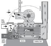
The Master Temp 400 has an internal bypass:
1714575825618.png

This is much better than heaters without a bypass such as most heat pumps but not as good as an external bypass.

To give you an idea of performance difference in a similar setup to yours, with the heater in-line and the pump at full speed, the operating point would be around:

107 GPM @ 69' of head & 2412 Watts

With the heater externally bypassed:

124 GPM @ 62' of head & 2613 watts

If you reduced the RPM (2975) of the external bypass scenario such that the flow rate is the same as without an external bypass, the operating point becomes:

107 GPM @ 46' of head & 1719 Watts

So you can either get more flow rate or fewer watts or a combination of both with the bypass.

Savings are much less at lower RPM.

But the other reason to have a bypass is so you can isolate the heater should you even need to a harsh chemical treatment of the water and/or maintenance on the heater.
 
That $1,000 include all parts - actuator, diverter, check valve, PVC? That is $500 - 600 in parts. Include connection and setup in your IntelliCenter? Maybe 2 hours of labor.

Put it in. It will make a big difference every day in the speeds you can run your pump and lower your electric cost.

Thanks for the prompt reply. All they said is $1,000 via text message. I assume that includes everything. I also heard back on the pump credit and it's $1,372 so that would more than cover the cost of the bypass. I just hope that there is enough room on the equipment pad to support the bypass setup as it seems a little cramped already.
 
The Master Temp 400 has an internal bypass:

View attachment 569284

This is much better than heaters without a bypass such as most heat pumps but not as good as an external bypass.

To give you an idea of performance difference in a similar setup to yours, with the heater in-line and the pump at full speed, the operating point would be around:

107 GPM @ 69' of head & 2412 Watts

With the heater externally bypassed:

124 GPM @ 62' of head & 2613 watts

If you reduced the RPM (2975) of the external bypass scenario such that the flow rate is the same as without an external bypass, the operating point becomes:

107 GPM @ 46' of head & 1719 Watts

So you can either get more flow rate or fewer watts or a combination of both with the bypass.

Savings are much less at lower RPM.

But the other reason to have a bypass is so you can isolate the heater should you even need to a harsh chemical treatment of the water and/or maintenance on the heater.

Thanks. So it sounds like most people here are in favor of the bypass. My only concern outside of the additional $1,000 is that this builder doesn't typically install these so I hope they will install it correctly and is there enough room on the pad to add it. I know the SWG needs to be at least 3 feet from the heater output and it's currently just over 3 feet today.
 
There is plenty of room to install the heater bypass if they are creative.

The SWG can be installed in a vertical loop which creates lots more space.
 
  • Like
Reactions: DSMinAtlanta
Update:

They installed the bypass last week. Prior to that, they were having issues getting the heater to ignite and had to call a Pentair rep to help. When the bypass was installed, supposedly the Pentair rep helped troubleshoot the heater and the builder says it was just "air in the gas line" and that "everything works now". So today we decided to test the heater and bypass to make sure it's all working and I'm really confused.

According to the install guide for the Pentair bypass, the IntelliValve positions should be at 0 and 7 when the heater is to the left of the valve: https://www.pentair.com/content/dam...heater_auto_bypass_valve_replacement _kit.pdf

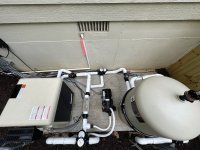
However, it seems that they set it up as if the heater is to the right of the valve (positions 24 and 17). When I fired up the heater, the IntelliValve did change positions and the heater ignited just fine but I didn't see much water flow through the check valve. There was some water going through as my wife said the water was warm coming into the pool. So I decided to follow the instructions and change the positions to 0 and 7. When I turned the heater back on via IntelliCenter, there was much more water flow through that check valve but after the heater fired up, there was a knocking sound (sounded almost like marbles inside the heater) and it shut off. I've got to get the builder back out here but before I do, I wanted to get the expert opinions of those here so I can present them with a plan to get this fixed the right way. Here is a picture of the equipment pad with the bypass installed. Can someone please help me figure out the CORRECT IntelliValve configuration for our pool?

In other news, I did jump into the pool for the first time after getting frustrated with all these equipment issues and it was amazing. :)


pool_equipment_1.jpg
 
24 & 17 settings are correct.

24 when the heater is on and 17 when the heater is bypassed.
 
24 & 17 settings are correct.

24 when the heater is on and 17 when the heater is bypassed.
Then are the Pentair instructions incorrect? In the manual I linked to, it says the settings should be 0 and 7 when the heater is to the left of the valve. Plus, you can barely see any water flowing through that check valve when running the heater and the flap in the check valve is only partially open. If all of the water is flowing through the heater when it’s on then I would expect that check valve to be filled with water.
 
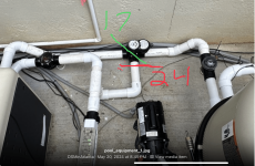
24 & 17 are correct.

See the pic below.

24 places the diverter blocking the bypass line as shown by the red line for when the heater is running.

17 allows water to flow through the heater and bypass, with most water going through the bypass, as shown by the green line when the heater is off.

The writer of the Pentair installation document made it overly confusing with the left/right when the bypass can be done in many different orientations.


1716338429345.png
 
  • Like
Reactions: DSMinAtlanta
24 & 17 are correct.

See the pic below.

24 places the diverter blocking the bypass line as shown by the red line for when the heater is running.

17 allows water to flow through the heater and bypass, with most water going through the bypass, as shown by the green line when the heater is off.

The writer of the Pentair installation document made it overly confusing with the left/right when the bypass can be done in many different orientations.


View attachment 575259
Thank you! So in my setup, the red LEDs for the bypass indicate water flow direction. On the other hand, the actuator for our water feature is configured where the red LEDs indicate where the water is NOT flowing. For example, if you look at the picture above, the IntelliValve at the bottom is currently set with the water feature off and the red LED is all the way on the side where the plumbing returns are for the feature wall. This is definitely really confusing given the Pentair guide. I really appreciate your help! I will test the heater again just to make sure it stays running in this configuration.

Edit: I think I'm confusing myself here. The red LEDs indicate how much flow is restricted based on their position? Is that the best way to think of it?
 
Last edited:
The red LED indicated the diverter position that is blocking flow in that direction.

You place the red LED on the pipe you do NOT want flow through.
 
  • Like
Reactions: DSMinAtlanta

Enjoying this content?

Support TFP with a donation.

Give Support
When I turned the heater back on via IntelliCenter, there was much more water flow through that check valve but after the heater fired up, there was a knocking sound (sounded almost like marbles inside the heater) and it shut off.
What you describe here is what occurs when there is not enough water flow to the heater. Sending all the water to the heater will resolve this issue.
 
  • Like
Reactions: DSMinAtlanta