16 July 2024 Finishing Up my OB Pool

I am also going to add that the above should be done even if there is a "hired pool builder". No you should not HAVE to do it but time and time again I have seen where there is little or no oversight by the "hired pool builder". The crew shows up and does their thing without any input from anyone. The pool owner is hoping they do it the correct way and follow the plans.

We had one pool that had a beach entry for their handicapped child. The concrete shell people did not do it! They made that area with the coping just like the rest of the pool. Fortunately the pool owner was there and caught it before the concrete set up. They were able to fix it fairly easy.
 
  • Like
Reactions: setsailsoon
Another source for CO2 is greenhouse supply stores I used to pick up 20 lb tanks for about $20 or less. But that was for my eight tap bar in the basement so 20 lb was good for several years. Plus I got all my tanks for free take a look on craigslist or Facebook marketplace I just found old expired tanks I got them for free and then exchanged them for a new one at the greenhouse supply store.
 
Another source for CO2 is greenhouse supply stores I used to pick up 20 lb tanks for about $20 or less. But that was for my eight tap bar in the basement so 20 lb was good for several years. Plus I got all my tanks for free take a look on craigslist or Facebook marketplace I just found old expired tanks I got them for free and then exchanged them for a new one at the greenhouse supply store.
Great info Dave, thanks!
 
29 April 2024 : People do projects

Folks,
Spoke with my tile guy today... he sounded terrible and was on his way to the doctor... another delay. As bad as I want to start this tile work he was pretty sick and needed to stay home. I still have a small chance to start in April!

Also, got my equipotential bond inspection this morning (passed). I also have to give Doheny's an attaboy. As mentioned in a previous post I was trying to go with their Harris vs pump to save a little money and connect with an adapter to convert to digital inputs since it doesn't have an RS 485 interface. Well my adapter doesn't fit on their pump. So called this morning and they said so long as the pump hasn't been installed they'd take it back. Also, offered that they'd send me their shipping label for $25. This is way cheaper than I could do. So went ahead and bought the Pentair 1.5 hp vs pump. I'm sure I'll be happier with this and now it will be easy to set up with both pumps on the Pentair RS485 protocol... it's only money. Surprisingly Robin was very supportive. She said "why wouldn't get the best pump on this fantastic pool?". Wow! I think she's been colluding with @Jimrahbe.

Chris
 
Last edited:
  • Like
Reactions: kimkats and JamesW
Pentair pump setup question.

I see in the manual it says I can set two addresses for the rs485 controlled pumps. It's right after they tell how to set the date and indicates if I lose power date is retained for 24 hrs. Is that the same for the pump address? @Jimrahbe @ajw22?

Chris
 
Chris,

I don't know for sure, but I have yet to see a thread complaining about the pump address going away, after a power outage.

Also, when the pump is shipped the default address is #1.. I'm sure in transit, the pump has no power for much longer than 24 hours, yet the address is always still #1.

Thanks,

Jim R.
 
  • Like
Reactions: setsailsoon
Chris,

I don't know for sure, but I have yet to see a thread complaining about the pump address going away, after a power outage.

Also, when the pump is shipped the default address is #1.. I'm sure in transit, the pump has no power for much longer than 24 hours, yet the address is always still #1.

Thanks,

Jim R.
Thanks Jim, power is pretty unreliable here and heading into storm season so I'm thinking I just put a note in the breaker panel that the main pump and filter pump need to have address checked after power failure plus note which one is which. The RPi will reboot when power is back but it's not gonna work too well if both default to #1. I guess if this is a problem I could always use digital inputs to control the filter pump. Nice to have both options.

Chris
My features pump maintains the address after hibernating all winter with the power disconnected. Should be good to go.

--Jeff
 
  • Like
Reactions: setsailsoon

Enjoying this content?

Support TFP with a donation.

Give Support
My features pump maintains the address after hibernating all winter with the power disconnected. Should be good to go.

--Jeff
That should work fine then. My most common case is a day or less on genset where the pool equipment is disconnected via load shedding module. Worst case is several weeks after a bad storm.

Thanks much!

Chris
 
No!!! Do not plug 24v into the USB C. You will not power the Pi directly.

You will send power to the MegaBas board. There is one of those plug in style connectors. I think it is the only 2 wire one. The MegaBas can take 24v AC or DC power and then power the rest of the hats and the Pi.

View attachment 566037
Andy,

I'm setting up the mock install of the Power and Control Boxes today. I'll be powering up the using 24vac as highlighted above. Is there a document that shows where I plug in the valve actuators and inputs? Or is that configured using the MEP application? I'm looking for basic stuff like where does the connector plug in for pool/spa mode valves etc. Box with the RPi stack, 10 6amp mini relays, and power distribution is shown below. For the valve actuator outputs I plan to gang the common using one of those jumper strips to simplify and neaten wiring. I plan to do all LV power distribution with shielded stranded 22/4 cables. Will connect outputs this way as well. Does this make sense to you?

As always, your help is much appreciated. I can't wait to get this running and let Robin play with it on her devices. After this is up, running, and reliable I'll try to get Home Assistant running on the Fire tablet.

Chris
 
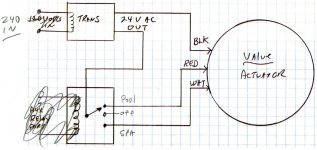
First get some Din rail terminal blocks. That will clean up your wiring and make this easier to distribute power. So every relay has 3 connections. That is for the NO/NC. 1 relay will power 1 actuator. I use @Jimrahbe wiring diagram as my go to reference.

img080-1.jpg
 
There is a 3 wire connector that will plug into the valve actuator connected. I should have given you some connectors while you were here. But they are pretty cheap on Amazon (I think I got them on Amazon). Let me look up the exact model.

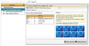
You configure the relay in the REM. Which is accessed by YourIPAddress:8080

You should get something like this. Click on the little gear to name and activate each relay. This will make them available to the Nixie where you can configure them for what they do. That is where you will configure your circuits, valves, aux circuits. That stuff mirrors what an Intellicenter looks like so you should understand it. I am actually not the best at it since that design seems counterintuitive to me. But there are lots of experts here that can help.

Edit found it: JST XH 2.54MM 3 Pin

Relay Equipment Manager.jpeg.png
 
The connector used on actuators is the JST XH 2.54MM 3 Pin available on Amazon and electronic supply houses.

The punch-down JST connectors are colored differently (white/maroon/black) depending on the wire gauge they can accommodate, so be careful to get the black ones.

 
I am pretty sure these are the terminal blocks that I got:


Make sure you order some jumpers so you can link some together (makes life easier).

I ordered black and red blocks to keep my +/- straight. Although you really dont have +/- for AC but you know what I mean.
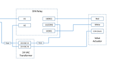
Below is wiring plan for distribution right now. Make sense?
  • Using the distribution blocks that gang each output from 24 vac (+,-, gnd) at the bottom. So each gang has 4 outputs for each power level.
  • Right now for the RPi and actuators all I need is 24vac.
  • Later I'll need a 12v gang for the 3 separate light circuits. Color will be changed by pulsing the 12 v signal.
  • I have 2 sets and have the jumpers arriving this morning for the relays.
  • Was planning to jump the common across the relays to reduce wire runs from terminal blocks
  • Wiring diagram looks like this (Relay terminal key below from each relay):

1714486095249.jpeg1714481862614.png
 
There is a 3 wire connector that will plug into the valve actuator connected. I should have given you some connectors while you were here. But they are pretty cheap on Amazon (I think I got them on Amazon). Let me look up the exact model.

You configure the relay in the REM. Which is accessed by YourIPAddress:8080

You should get something like this. Click on the little gear to name and activate each relay. This will make them available to the Nixie where you can configure them for what they do. That is where you will configure your circuits, valves, aux circuits. That stuff mirrors what an Intellicenter looks like so you should understand it. I am actually not the best at it since that design seems counterintuitive to me. But there are lots of experts here that can help.

Edit found it: JST XH 2.54MM 3 Pin

View attachment 568987
Very helpful, thank!

Yes, I think they were the small green connectors. I plan to use a two conductor one to supply power to the megabas as you described earlier.

Chris
 
Just a note. The relays on the hat are fine for running the actuators directly.

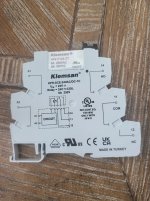
The picture of the relay you have in your post is what I use for high voltage. Ie supplying power to the heater and SWG. I use the relays on the hat to fire the high voltage relays. So I only have two of those, 1 for heater power, and 1 for SWG power. Everything else is wired directly off the hat.
 
Below is wiring plan for distribution right now. Make sense?
  • Using the distribution blocks that gang each output from 24 vac (+,-, gnd) at the bottom. So each gang has 4 outputs for each power level.
  • Right now for the RPi and actuators all I need is 24vac.
  • Later I'll need a 12v gang for the 3 separate light circuits. Color will be changed by pulsing the 12 v signal.
  • I have 2 sets and have the jumpers arriving this morning for the relays.
  • Was planning to jump the common across the relays to reduce wire runs from terminal blocks
  • Wiring diagram looks like this (Relay terminal key below from each relay):

View attachment 569017View attachment 569004

Not sure I understand the purpose of the fuse on the secondary side of the transformer … what are you trying to protect?
 
  • Like
Reactions: Katodude

Enjoying this content?

Support TFP with a donation.

Give Support