Screenlogic wireless no longer active

Kjhoffman

Gold Supporter
Jul 4, 2017
92
Bradenton
My screenlogic stopped communicating to my easytouch system recently. It seems to receive correct information from ET (pool water temp, circuits running etc) but does not communicate changes I make with the App or the Windows interface. For example, i turn on Spa and the button on the windows screen turns green. The spa never actually comes on. But after about 5 to 10 seconds the screen button just turns itself off and goes back to grey. I have seen similar posts but following the recommended troubleshooting leads me to another question.

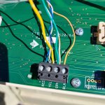
As suggested I plan to hardwire the protocol converter into ET to bypass the wireless link. When I remove the low voltage panel I see 6 wires going into the 4 wire block. I am not sure what the other 2 wires are for and hesitate to just remove them for my test. Any thoughts on the other 2 wires ?

.
 

Attachments

  • 20240210_120036[1].jpg
    20240210_120036[1].jpg
    635.9 KB · Views: 18
Other 2 wires are RS-485 data lines to another device.

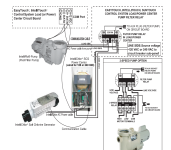
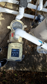
You have two devices wired to that comm block.

You have a VS pump or Intellichor SWG?
 
The WhisperFlo VS is communicating as well as the SWG.

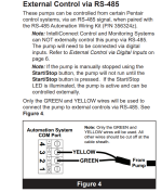
The pump should only use the two center wires.

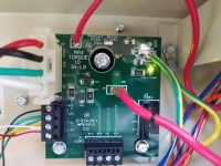
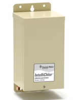
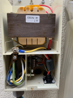
Can you show the wiring in the SWG control power box?

Pentair Whisperflo VST 2.6HP (Nov 2022), H400 Gas heater, Pentair EasyTouch system added in 2012.

Screenlogic interface added 2019.

1707590832303-png.553582


22.jpg20230220_102255[1].jpg
1707591266606.png
 

Attachments

  • 1707590832303.png
    1707590832303.png
    1.2 MB · Views: 49
If a piece of equipment has its own power supply, then you typically do not use the power wires #1 ground black or #4 (15 volt) red and you only use the two center data wires #2 (-DT) Green and #3 (+DT) Yellow.

You might not want the two power wires connected.

The power wires would only be used for an external device like a Spa Side Controller that did not have its own power supply.

It is always best to follow the manufacturer's color coding to avoid mixing up the wiring from one side to the other.

Check all wiring to make sure that it is correct.

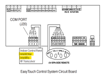
The J20 is the COM port where the pump and Intellichlor connect using the green and yellow center wires.

CAUTION - Wire the Power Center AC to the filter pump relay on the LOAD SIDE for maximum safety.

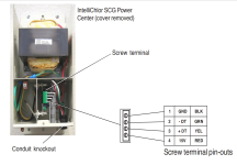
To connect IntelliChlor Power Center four wire cable to the IntelliTouch, EasyTouch or SunTouch Control System
load center:

1. Remove the cover screw securing the Power Center cover. Remove the cover.

2. Run a UL approved four conductor cable (22 AWG) from the IntelliChlor Power Center to the Load Center.

The preferred wire color scheme is red, yellow, green, and black.

3. Remove the cover screw securing the Power Center cover.

Remove the cover.

4. Remove one (1) of the knockouts from the underside of the Power Center.

5. Route the four conductor cable up through the lower hole.

6. Strip back the cable conductors 1-1/4 in. Insert the wires into the screw terminals (provided in the kit).

Secure the wires with the screws.

Make sure to match the color coding of the wires:

Red = +15, Yellow = +DT, Green = -DT, and GND = Black.

7. Plug the screw terminal onto the four (4) pins located on the Power Center board.

8. Reinstall the cover and secure with the cover screw.

9. Proceed to “Connecting IntelliChlor to an IntelliTouch Control System,” on page 25, “Connecting IntelliChlor to an EasyTouch Control System,” on page 26, and “Connecting an IntelliChlor SCG to a SunTouch Control System,” on page 26.

Connecting IntelliChlor® SCG Communication Cable (RS485):

1. Unlatch the load center/power center enclosure door spring latch, and open the door.

2. EasyTouch® / IntelliTouch® Control System: Loosen the two (2) retaining screws from the control panel.

(a) Lower down the control panel on its hinges to access the motherboard located behind the control panel.

(b) Route the four conductor cable up through the low voltage raceway in the load center to the
motherboard.

Note: For SunTouch® Control System see page 26 for details.

3. Strip back the cable conductors ¼ in. Insert the wires into the connector screw terminals (provided in the kit).

Secure the wires with the screws.

Make sure to match the color coding of the wires; Red = +15, Yellow = +DT, Green = -DT, and GND = Black.

4. Insert the connector screw terminal onto the COM Port pins on the circuit board: (EasyTouch J20, IntelliTouch J7/8).

7. When the connection is completed: EasyTouch/IntelliTouch: Close the control panel and secure it with the two (2) retaining screws.

8. Close the load center front door.

Fasten the spring latch.

1707591502358.png

1707591805608.png


1707591909753.png
 

Attachments

  • IntelliChlor_Owners_Manual_Version_3_units_after_Nov_2011_English.pdf
    1.6 MB · Views: 0
All of my wiring was done in initial ET install by electrician. I agree the wire colors should have been done per the install documentation. I guess he had some spare wiring he used instead. Since everything had been working for years Im not really looking to change anything. But I wanted to hardwire screenlogic protocol adapter to ET to see if my wireless transceiver is the problem. I think I will instead wire protocol adapter the the wiring block in the outdoor transceiver. Is that going to achieve the same result ?
 

Enjoying this content?

Support TFP with a donation.

Give Support
I don't have a saltwater pool. I'm a little confused not really sure what the attached pics are (I didnt attach them)
You had posted earlier for a neighbor.

I confused the post and pictures with your pool.

This is not a question on my pool, but rather for my neighbor who just had new pool installed.

Can you show your equipment?

What do the wires go to?
 
Oh now i get it :).

I could send pics but basically all Im trying to do is hardwire my screenlogic protocol adapter to determine if the comms problems are due to the outdoor transceiver. I have no other equipment issues just the screenlogic interface which had been working for years and recently stopped communicating.
 
  • Like
Reactions: JamesW
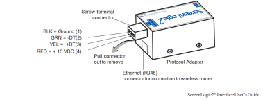
To connect to the Protocol adapter:

1. Connect the Four-Conductor Cable: Run a four conductor cable (22 AWG UL approved) from the Load Center or Power Center location to the adapter.

The pin numbers and wire color codes are:
1) BLK = Ground
2) GRN = -DT
3) YEL = +DT
4) RED = +15 VDC

1707595199662.png
CAUTION Do NOT short GND or +15 VDC connections (Red or Black) to data lines (Green or Yellow).

The Personality board may be permanently damaged.

Do NOT reverse GND or +15V or system will not operate.


Attachments

  • screenlogic2-interface-installation-users-guide-english.pdf
    2.6 MB · Views: 1
Last edited:
The simple approach to SL issues literally unplug your power supply inside wait 10 seconds and plug back in. Then go to outside panel and hit reset button and wait a bit. Your antenna outside and inside should have all lights blinking in a series. One solid green then blinking green then orange. On both antennas. If they aren't doing a sequence every few seconds it's most likely a loose wire somewhere (usually at the com port behind board) or the protocol adapter needs to be updated. Try to log in remotely and if it's works then it may be your home internet. Also interesting tid bit. If you use a Sonos or any other kind of mesh network you need to plug screen logic cat 5 cable into that and not your main router. The Sonos and other systems will sometimes block the SL signal if plugged in elsewhere thinking it's a threat. I've done over 300 SL installs. With all the new tech coming out pentair is falling behind on things. The new intellicenter is slightly better as the protocol adapter is no longer but still uses same wireless antenna kit. SL can be really finnicky and annoying. Try a reset first.
 
The simple approach to SL issues literally unplug your power supply inside wait 10 seconds and plug back in. Then go to outside panel and hit reset button and wait a bit. Your antenna outside and inside should have all lights blinking in a series. One solid green then blinking green then orange. On both antennas. If they aren't doing a sequence every few seconds it's most likely a loose wire somewhere (usually at the com port behind board) or the protocol adapter needs to be updated. Try to log in remotely and if it's works then it may be your home internet. Also interesting tid bit. If you use a Sonos or any other kind of mesh network you need to plug screen logic cat 5 cable into that and not your main router. The Sonos and other systems will sometimes block the SL signal if plugged in elsewhere thinking it's a threat. I've done over 300 SL installs. With all the new tech coming out pentair is falling behind on things. The new intellicenter is slightly better as the protocol adapter is no longer but still uses same wireless antenna kit. SL can be really finnicky and annoying. Try a reset first.
Thanks srqpoolguy. btw Im also in SRQ. I appreciate the suggestions. I have tried unplugging, resetting the adapter. powering down router etc. Nothing seemed to fix it. The SL has been working for 4 years. I do have it plugged in to router in my orbi mesh network. It has worked fine till recently so Im thinking a wireless radio issue, possibly a loose wire. I'll go check the ET board to see if a wire came loose.

On both indoor and out I was seeing a solid light and blinking green and orange tx/rx lights. However on indoor unit, after about 20 seconds solid green light begins blinking slowly then rapidly then becomes solid again. So it appears it tries to communicate and detects a lost signal and tries to correct it.

in the SL windows app Home screen I see stats such as sir temp, last pool temp etc, but if I click the "fish" to go to into the settings I just get "connecting to pool controller" message.

Appreciate your thoughts..
 
When I use mobile app I can go to circuits and turn on/off. For example I turn on Pool. It stays "lit" in the App so SL knows I turned it on. Then I see in the Windows app that the Pool circuit is on. The Pool (pump) does not actually turn on but SL believes it is on so SL is not sending the commands to ET (or ET has a connection issue). So my question is, where are these settings being stored that allows the Windows app to be aware of the circuit being turned on from another interface?
 
So my question is, where are these settings being stored that allows the Windows app to be aware of the circuit being turned on from another interface?
The apps all get their data feed from the Protocol Adapter.

The PA translates EasyTouch panel signals into data the apps can read.

Your PA is alive and responding but it is not communicating with the ET panel.
 
thanks. I guess Im still confused so forgive my question if a silly one;

I understand the PA translates and provides data via wireless to the panel. I didnt think the PA would retain the data/state, so if not communicating to the panel, when I start the windows app how does the windows app know the pool is "on" ? Does the PA actually store this information as well?
 
Does the PA actually store this information as well?
My understanding is yes, the PA stores state data.

App control over old pool equipment is a kludge as the EasyTouch system is a 1980s design. That is why Pentair has declared it obsolete.
 
  • Wow
Reactions: JamesW

Enjoying this content?

Support TFP with a donation.

Give Support