Automation of INTEX SWG

Ok, I spent WAY to much time last evening/night with my logic analyzer, looking at the communication between the main, and display board, on my non TM1650 Intex SWG! But I've managed to completely reverse engineer the protocol, in both directions!
I'm able to control the LEDs on the display board from an ESP32, and read the buttons.

But I might be over my head with integrating this knowledge, with the code from @tonyflores1006, as I haven't used Visual Studio Code / ESP-IDF to write code for ESP32 before. I'll see what I can figure out...
 
  • Like
Reactions: jressel01
If you send me the Dokumentation i can try to help you.
we can make a Config entry wich board we have with only one Code.
In my Fork @github i make changes on the code because i have some problems
 
If you send me the Dokumentation i can try to help you.
we can make a Config entry wich board we have with only one Code.
In my Fork @github i make changes on the code because i have some problems

I'll see if I can write something down.

I've already changed the way I think of the signals to make it easier to decode them. I've got sample code that controls the 7-segments, and code that transmits simulated button presses to the main board.

The only thing left is to write something that decodes the signals from the main board to the display board, as intercepting and understanding this is the only way for the ESP32 to figure out the state of the SWG. Probably the most complicated part.

Thanks for linking in your fork, I see you have cleaned things up a bit. Why do you recommend changing the relay to GPIO2 ? I can update the PCB if necessary?
It might also be wise to link to the "Jumper version" of the PCB, as it will work for booth types of SWG. Just two extra jumper wires to solder, if you don't want pin-headers.

The only reason I linked in the TM1650 version, was that I hadn't tested the Jumper version yet, which I've done now.

It might be easier to write new code to control the non TM1650 SWGs though. I'll assume it wil be complicated to use @tonyflores1006 's code without a complete rewrite. But I haven't looked at it yet, still figuring thing out...
 
I've released the documentation on the non TM1650 protocol, and some code samples that allows for the decoding of the traffic between the the main board, and the display board. It's also possible to emulate keypresses on the buttons. As the display board is "stateless", any code need to track the current state of the swg, based on the communication between the display board. It'll be complicated, and a lot of work (impossible?) to integrate this with the code from @tonyflores1006. Might be easier to start from scratch, based on my samples?
Hopefully, someone with a bit more coding experience, at least with Visual Studio Code / ESP-IDF can have a look at it? @jressel01

The protocol/samples is located at intex-swg-pcb/protocol at main · jingsno/intex-swg-pcb
(Please excuse the mess, I finished the samples 10 days ago, and haven't cleaned up the code/comments)

Edit: I see all almost all the samples are missing setting the data lines HIGH on ESP32 boot:

digitalWrite(TO_DISP, HIGH); // sets the TO_DISP signal to HIGH
digitalWrite(TO_MAIN, HIGH); // sets the TO_MAIN signal to HIGH

Fixet, and updated repository
 
Last edited:
Below is a sample of the serial output. Observe that when a LED is blinking, the mainboard sends the whole data structure again, and again, with just one bit toggled.

FROM_MAIN (Pin 18) Configured for main board input.
FROM_MAIN (Pin 18) ISR0 function attached.
TO_DISP (Pin 16) Configured for display board output.
FROM_DISP (Pin 17) Configured for display board input.
FROM_DISP (Pin 17) ISR1 function attached.
TO_MAIN (Pin 19) Configured for main board output.
[Power]
[0 8 ] LED: POWER=ON SLEEP=OFF PUMP_LOW_FLOW=OFF LOW_SALT=OFF HIGH_SALT=OFF BOOST=OFF SERVICE=OFF OZONE=ON 3F7F0C00
[Button Release]
[0 8 ] LED: POWER=OFF SLEEP=OFF PUMP_LOW_FLOW=OFF LOW_SALT=OFF HIGH_SALT=OFF BOOST=OFF SERVICE=OFF OZONE=ON 3F7F0400
[0 8 ] LED: POWER=ON SLEEP=OFF PUMP_LOW_FLOW=OFF LOW_SALT=OFF HIGH_SALT=OFF BOOST=OFF SERVICE=OFF OZONE=ON 3F7F0C00
[0 8 ] LED: POWER=OFF SLEEP=OFF PUMP_LOW_FLOW=OFF LOW_SALT=OFF HIGH_SALT=OFF BOOST=OFF SERVICE=OFF OZONE=ON 3F7F0400

[Power]
[ . ] LED: POWER=OFF SLEEP=OFF PUMP_LOW_FLOW=OFF LOW_SALT=OFF HIGH_SALT=OFF BOOST=OFF SERVICE=OFF OZONE=OFF 80000000
[Button Release]
[Power]
[0 8 ] LED: POWER=ON SLEEP=OFF PUMP_LOW_FLOW=OFF LOW_SALT=OFF HIGH_SALT=OFF BOOST=OFF SERVICE=OFF OZONE=ON 3F7F0C00
[Button Release]
[0 8 ] LED: POWER=OFF SLEEP=OFF PUMP_LOW_FLOW=OFF LOW_SALT=OFF HIGH_SALT=OFF BOOST=OFF SERVICE=OFF OZONE=ON 3F7F0400
[Lock]
[ ] LED: POWER=OFF SLEEP=OFF PUMP_LOW_FLOW=OFF LOW_SALT=OFF HIGH_SALT=OFF BOOST=OFF SERVICE=OFF OZONE=ON 400
[Button Release]
[0 8 ] LED: POWER=ON SLEEP=OFF PUMP_LOW_FLOW=OFF LOW_SALT=OFF HIGH_SALT=OFF BOOST=OFF SERVICE=OFF OZONE=ON 3F7F0C00
[ ] LED: POWER=OFF SLEEP=OFF PUMP_LOW_FLOW=OFF LOW_SALT=OFF HIGH_SALT=OFF BOOST=OFF SERVICE=OFF OZONE=ON 400
[Timer]
[0 9 ] LED: POWER=ON SLEEP=OFF PUMP_LOW_FLOW=OFF LOW_SALT=OFF HIGH_SALT=OFF BOOST=OFF SERVICE=OFF OZONE=ON 3F6F0C00
[Button Release]
[ ] LED: POWER=OFF SLEEP=OFF PUMP_LOW_FLOW=OFF LOW_SALT=OFF HIGH_SALT=OFF BOOST=OFF SERVICE=OFF OZONE=ON 400
[0 9 ] LED: POWER=OFF SLEEP=OFF PUMP_LOW_FLOW=OFF LOW_SALT=OFF HIGH_SALT=OFF BOOST=OFF SERVICE=OFF OZONE=ON 3F6F0400
[Timer]
[1 0 ] LED: POWER=ON SLEEP=OFF PUMP_LOW_FLOW=OFF LOW_SALT=OFF HIGH_SALT=OFF BOOST=OFF SERVICE=OFF OZONE=ON 63F0C00
[Button Release]
[ ] LED: POWER=OFF SLEEP=OFF PUMP_LOW_FLOW=OFF LOW_SALT=OFF HIGH_SALT=OFF BOOST=OFF SERVICE=OFF OZONE=ON 400
[1 0 ] LED: POWER=OFF SLEEP=OFF PUMP_LOW_FLOW=OFF LOW_SALT=OFF HIGH_SALT=OFF BOOST=OFF SERVICE=OFF OZONE=ON 63F0400
[Timer]
[1 1 ] LED: POWER=ON SLEEP=OFF PUMP_LOW_FLOW=OFF LOW_SALT=OFF HIGH_SALT=OFF BOOST=OFF SERVICE=OFF OZONE=ON 6060C00
[Button Release]
[ ] LED: POWER=OFF SLEEP=OFF PUMP_LOW_FLOW=OFF LOW_SALT=OFF HIGH_SALT=OFF BOOST=OFF SERVICE=OFF OZONE=ON 400
[1 1 ] LED: POWER=OFF SLEEP=OFF PUMP_LOW_FLOW=OFF LOW_SALT=OFF HIGH_SALT=OFF BOOST=OFF SERVICE=OFF OZONE=ON 6060400
[Timer]
[1 2 ] LED: POWER=ON SLEEP=OFF PUMP_LOW_FLOW=OFF LOW_SALT=OFF HIGH_SALT=OFF BOOST=OFF SERVICE=OFF OZONE=ON 65B0C00
[Button Release]
[ ] LED: POWER=OFF SLEEP=OFF PUMP_LOW_FLOW=OFF LOW_SALT=OFF HIGH_SALT=OFF BOOST=OFF SERVICE=OFF OZONE=ON 400
[ ] LED: POWER=OFF SLEEP=OFF PUMP_LOW_FLOW=OFF LOW_SALT=OFF HIGH_SALT=OFF BOOST=OFF SERVICE=OFF OZONE=ON 400
[0 1 ] LED: POWER=OFF SLEEP=OFF PUMP_LOW_FLOW=OFF LOW_SALT=OFF HIGH_SALT=OFF BOOST=OFF SERVICE=OFF OZONE=ON 3F060400
[Power]
[ . ] LED: POWER=OFF SLEEP=OFF PUMP_LOW_FLOW=OFF LOW_SALT=OFF HIGH_SALT=OFF BOOST=OFF SERVICE=OFF OZONE=OFF 80000000
[Button Release]
 

Enjoying this content?

Support TFP with a donation.

Give Support
@jressel01 Can you give me the dump of what these two return on your TM1650 SWG?

Get current status GET http://ip_addr:8080/api/v1/intex/swg/status
Get current debug GET http://ip_addr:8080/api/v1/intex/swg/debug

On the Homeassistant Integration:
IntexSWG_on and IntexSWG_off controls the realy, or pushes the power button on the SWG? Likewise, what does IntexSWG_Standby do?
What modes can you set with IntexSWG_Mode ?
 
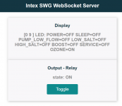
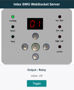
Some more progress. Needs a Wifi-Library, for easier WiFi config, and some interface for Home Assistant, to control it.
HA might be able to use the Websocket interface actually?. Implement MQTT maybe?

(Slight glitch on the enclosed gif-animation, on "12", as I had to much serial debugging turned on.)

IntexSWG.png
 

Attachments

  • IntexSWG.gif
    IntexSWG.gif
    938.1 KB · Views: 13
I have only one problem, my control panel is partialy broken. After connect to electricity, swtich are functional about few second and then switch on switch off, as if I pressed the lock button. Then is only possibility to turn on with two keys power + timer. The circuit will probably be defective.
 
So I'm about to put this stuff together finally but I wanted to run someing by tonyflores1006, jressel01 and/or Jings.

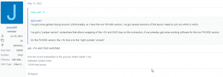
Seeing that I have a different model then you all I traced out the lines and found that my 5v is on the inside while the ground is on the outside. Looking at some convos:

1680714516974.png

that this would not be a TM1650 chip? Or am I reading that incorrectly?

a7qvl.jpg

The pink being the 5v and the blue being the ground.
 
Added some features in my development branch, made a web page displaying status, controlling the relay, and a feature for OTA updates

View attachment 421088
Hi @Jings, first of all I love the work you guys are doing on the SWG!

I have the PIC16F88 version of the SWG and saw on your github ( GitHub - jingsno/intex-swg-pcb: Intex SWG with jumpers ) this comment:
"Software for the "non TM1650" (18 pin) version of the display board is under development. (Current status of non released development version of the software, allows for fullt control of the Intex SWG from a web interface.)"

Is it possible that you could share the "non released development version"?

Tnx!
 
Hello @Jings

Thank you for the great project.
Unfortunately I am new with ESP32.

Is there an exact instruction how I get this on the esp32?
Or is it possible to share the BIN file?

Or would it be possible to use the project in ESPHome from HomeAssistant?

Thanks for the support.
 
Hy @Jings !

I really need your help, 'cause my SWG control panel died a week ago (randomly beeping, and resting). I want to make the ESP mod on that to try use it without the control panel, but I can't build the code from your GitHub. (lots of errors when I try to compile). Can you give some support on that?

Thanks a lot!

Regards,
István
I have found a solution.
You must use the version 4.2.2 from ESP to compile. And you must add the wifi-manager in the component folder.
Then it gives two problems when you compile but with the solution in the log.

Good luck.
 
  • Like
Reactions: SteveJoiner86
I have found a solution.
You must use the version 4.2.2 from ESP to compile. And you must add the wifi-manager in the component folder.
Then it gives two problems when you compile but with the solution in the log.

Good luck.
Thank you so much! I'll give it a try this weekend.

As far as I understand, you can compile it and it works? Which wifi-manager repo and which compiling environment are you using? I tried VSCode, ESP-IDE, ElcipseIDE but no luck...

Regards,

István
 

Enjoying this content?

Support TFP with a donation.

Give Support