
Overview
The Hayward Aquarite consists of two units:
- Control panel and power supply, typically wall mounted
- T-Cell for chlorine generation
The T-cells come in various generating capacities. The specific T-cell being used needs to be set in the control panel for proper operation.
The Aquarite design appears to be used in other manufacturers products including:
- Mineral Springs MS-10
- Carvin Saniclear 20
Basic AquaRite Diagnostics
This is the basic information we need to know in diagnosing a problem:
- Report all readings when you..
- Move the switch from auto to off and check all of the readings.
- Move the switch back to auto and recheck the readings.
- Move the switch to off for a minute and then back to auto and recheck the readings.
- What are the first seven characters of the cell and box serial numbers?
- What is the actual salinity and how are you measuring it?
Aquarite T-Cells
Cell chlorine Generating Capacity
Each cell T-3, T-5, T-9, T-15 will produce a specific quantity of chlorine before it is depleted.[1][2]
- T-3 = 210 pounds - 15,000 gallons
- T-5 = ??? pounds - 20,000 gallons
- T-9 = 385 pounds - 25,000 gallons
- T925 Extended Life = 480 lbs - 25,000 gallons
- T-15= 580 pounds - 40,000 gallons
- T940 Extended life - 725 pounds - 40,000 gallons
- Equivalent pounds of Trichlor produced over the lifetime of the cell with properly maintained cell and water chemistry.
T-Cell-3 = 0.53 lbs/day = 15k gallons, 210 lbs total trichlor equivalent lifetime.
T-3 = 193 lb chlorine gas lifetime or 364 days at 100% or 8,736 hours at 100%.
T-Cell-5 = 0.636 to 0.784 lbs/day = 18k to 20k gallons.
T-Cell-9 (925) = 0.98 lbs/day = 25k gallons, 385 lbs total.
t-9 = 354 lb chlorine gas lifetime or 361 days at 100% or 8,664 hours at 100%.
T-Cell-15 (940) = 1.47 lbs/day = 40k gallons, 580 lbs. total trichlor equivalent lifetime.
T-15 = 533 lb chlorine gas lifetime or 362 days at 100% or 8,688 hours at 100%.
Which T Cell Should I Buy?
TFP recommends you get a cell at least 2X your pool water volume. Manufacturers specifications assume you will run your pump 24/7 and have the cell generating 24 hours a day. Oversizing the cell allows reduced pump runtimes, reduced SWG %, and excess chlorine generating capacity if needed.
Not all cells, that are the same size, last the same amount of time in the real world is true due to many factors, but they should come very close to making the same amount of chlorine during that time. The ones that make less chlorine are most likely acid washed and each time they are acid washed they will lose some of their lifespan. If one uses a strong mix of acid to water then they can significantly reduce the lifespan.[3]
T-15 Cell Types
The Hayward T-Cell-15 and Hayward T-Cell-15-SWP are the same thing.
The T-Cell-15 has a 3 year warranty.
The Hayward T-Cell-15-SWP is a Swimpure branded cell, which has a 2 or 3 year warranty. You would need to verify with the seller to be sure.
The first number of the serial number is the length of warranty.
The TCELL940 is a T-15 "long life" cell with a 4 year warranty.
A T-15-W is a warranty replacement cell with a 1 year warranty. It's not designated as a retail cell. It's supposed to be used as a replacement for a cell that fails under warranty. Some places sell warranty cells as regular cells.
Generic T-15 Cell Replacements
Some people have had good experiences and saved money by buying a rebuilt cell or a generic cell.[4] Look for a company that rebuilds using high quality USA parts just like the original Hayward cell and specializes in rebuilding high quality electronics.
Members have had good experience with Salt Solutions T-15 cells[5] and the Chlorinator Pro CP-15 cell[6].
Be aware of the following issues buying the generic cells:
- The warranty is usually less then the OEM cell.
- The lifespan of generic cells are usually rated for less hours than the OEM cells, hence the shorter warranty times.
- To make a warranty claim you have to deal with shipping and all that goes with buying it online with a generic cell. With a OEM cell you can take it to an authorized dealer and they will replace it right then and there if it is a bad cell.
A member in the generic cell business warns about offshore companies "implying their cells are equal to the OEM but plates are only good for 3000 hours. (Because how would a buyer know...I've always had 7000 hr cells and Hayward is 10K). Misidentifying imported products to get around or reduce tariffs. Ordering one branded cell and receiving a different brand or even a different model and calling it a free upgrade. Offering ridiculous 5 or 7 year prorated warranties with no disclosure as to what the pro-rations are or that they are based upon some mythical MSRP. Unable to make a warranty claim because no one answers the phone, English is not their first language, or the warranty center is overseas. Their goal is to make you give up."[7]
AquaRite Low Salt Chlorine Generator
Hayward sells a low salt model outside the US. Primarily for the Canadian market. Certain communities in the Ontario area have passed low salt requirements for discharge into the sewer system. Toronto being one.[8]
The low salt unit is designed to make chlorine at low salt level without the unit showing a low salt level service light. It is only good on pools up to 25,000 gals. With low salt the unit will make less chlorine at the same set point as the standard model. You can also run the low salt unit at the same salt level as the standard unit.[9]
Specifications are:
- For in-ground pools up to 30,000 gallons
- Operates at just 1200 - 1800 ppm
- Uses the T-15 cell
To determine the total output (lbs chlorine gas) per day check the amps while running and multiply by 0.18.[10]
Determining Salinity
The AquaRite uses the performance of the cell to determine salinity. For each cell (T-3, T-5, T-9 OR T-15), Hayward knows the performance of a properly functioning cell at each temperature and salinity combination. The higher the salinity and/or water temperature, the higher the performance (chlorine output).
To get the performance of the cell, divide the instant salinity by the actual salinity. If the ratio is less than 75%, it's time for a new cell. For example, 2,000 (instant salinity) ÷ 3,600 (measured salinity with a test kit)=56%. Check the cell and clean it if necessary. If that doesn't work, it's time for a new cell.
There is no separate salinity sensor in an AquaRite. There are six wires going to the cell, two white, two black, one red and one blue wire.
The black and white wires carry the power to the cell and are heavier gauge than the other wires. The two white wires go to the center plate. The two black wires tie together and go to the two outer plates. The red and blue wires go to the temperature sensor.
There are no other wires going into the cell to support a salinity sensor. There are 4 extra wires in the cell cord (brown, orange, yellow and green) that are not used and do not go to the cell.
Another way to tell that the AquaRite does not have a separate salinity sensor is that if the T-Cell setting does not match the cell type, the salinity will read wrong.
If the Cell is larger than the T-Cell setting, the salinity will read higher than actual. If the Cell is smaller than the T-Cell setting, the salinity will read lower than actual. One can verify this by changing the T-cell type and see the salinity change.
If there was a separate salinity sensor in the cell, the salinity would not change when the tcell type was changed.[11]
Cell Diagnostics
Pressing the diagnostic button sequentially will display:
- Default salt display
- Pool temp
- Cell Voltage - When not generating, the voltage is about 30 to 32 volts dc. When generating, the voltage drops about 1 volt per amp of current.
- Cell current
- Desired output (% of the knob)
- Instant salinity
- Product name
- Software revision (r.XX)
- Cell type
The Hayward Aquarite Troubleshooting Guidelines explains each reading.
To estimate the performance of the Aquarite cell, divide the instant salinity reading by the actual salinity. If the performance is less than 75%, the cell is failing and it's time to replace it. You need to be sure about the actual salinity by using a salt test like the Taylor K-1766.
Check the instant salinity reading and then cycle power to reverse polarity and recheck the instant salinity reading. The numbers should be about the same +/- 200 ppm.
You can get the age of the cell from the serial number. It will be 3Exx, where xx is the year it was made.
Change Cell Type
With the correct cell in place, move the switch to auto and momentarily push the diagnostic button to display the cell type "T-X". Then move the switch to Superchlorinate and back to auto 3x or until T-15 or whatever the correct cell type is shown on the display.
Change Product Name
Move the switch to auto and momentarily push the diagnostic button to display the Product Name "AL-X".[12] Then move the switch to Superchlorinate and back to auto 3x or until the desired AL-X is shown on the display.
- AL-0 is AquaRite
- AL-1 NatureSoft
- AL-2 MineralSprings
- AL-3 SmartPure
- AL-4 This changes the default display from average salt to percent output.
- AL-5 This is used with Jandy automation.
COLD Water Temperature
- The cell output reduces to 20% at 60°F and below if % is above 20%
- The cell shuts off when water temperature at 50F and below
- LCD displays COLD when water temperature is below 50F
HOT Water Temperature
LCD display will read “HOT” when the water temperature is above 140 oF.
If the water temperature reads greater than 140o F, the cell temperature sensor is shorted and the cell needs to be replaced. It may be a problem with the temperature sensor in the cell or a problem with the circuit board reading the temperature sensor.
If you have a multimeter, you can check the resistance of the thermistor in the cell. See below for the Aquarite T-Cell cable plug configuration to test.
Thermistor
How the Thermistor Works
The thermistor protects the electronics and transformer from excessive inrush current. Inrush current depends on what part of the sine wave the ac voltage is in when power is turned on.[13]
If the voltage is zero, the inrush current can be very high and overload the electrical components. The thermistor provides a temporary resistance to control inrush current. Basically, it acts as a surge protector.
The AS32 2R025[14] will get up to 428 °F at its full current rating of 25 amps. However, there should not be that much current going through the thermistor while operating. It is designed to heat up while operating, so it does get hot.[15][16]
The control board sets the amps based on the cells salinity reading. Higher salinity will generate higher amps. Amps over 8 can overheat the thermistor. If the amps are 8.0 or higher after you replace the thermistor, you should reduce the salinity to prevent repeated failures.[17]
Failure Modes
The thermistor is pretty much the only thing that fails in the AquaRite power box. It stays hot the entire time it's generating. However, it's only needed during the first few seconds of operation.[18]
Symptoms of a bad thermistor include no power and chlorinating light, no power to salt cell.[19]
When the thermistor begins to fail, the voltage gets erratic.[20] Zero volts points to a bad thermistor.[21]
The thermistor used to limit inrush current (the "big black disc") usually blows after a power surge, typically brought on by a storm or utility glitch.[22]
Diagnostics
Usually you can see cracks in the coating on the thermistor indicating it’s bad. Some have looked normal and couldn’t find any cracks - but they were bad. Don't bother testing them because in order to access the thermistor...everything else is removed, it wouldn’t take much longer to just replace it.[23]

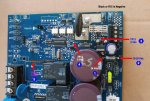
If the thermistor is good, the voltage reading on the display matches the measured voltage from the thermistor lead farthest from the Red terminal on the board as shown. Make sure the Blk test lead is on the Negative side (not Ground) which is the black terminal or to the R15 (.015 Ω) link as shown in the pic.[24]
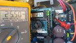
The thermistor on the SWG is a Negative Temp Coefficient (NTC) thermistor, so resistance will decrease as temp increases. The rating for the thermistor is 2 ohms at room temp (low 70’s F), which is about the reading you should get on a multimeter, give or take a little depending on temp. If it’s wayyy off, it’s bad. If it’s close, proceed.
The next test is, while holding the two leads of the multimeter on the legs of the thermistor, apply a heat source (hair dryer, heat gun, etc.) for a few moments. The resistance reading should begin to drop as the heat source is applied. If not, it’s bad.
A thermistor hack is to put a binder clip on it. It holds it together and acts like a heat sync. If the binder clip test makes it work, then you know your thermistor has done gone bad. You can leave the binder clip on while you wait for a new thermistor to arrive.[25]
Thermistor Replacement
Thermistor is a AS32 2R025.[26]
The part cost is $2.50 and the repair takes about 15 min. You can cut the legs of the old one and solder the new one to them at a 90 degree angle standing away from the board. It's easier to do and allows for better cooling.[27]
Screw Terminal for Thermistor
One member used a screw terminal (Digi-Key part# ED2561-ND) to mount the thermistor on. This should enable replacing the thermistor in the future without having to solder. The original thermistor is AS32 2R025 which has a wider lead wire footprint but the available replacement on hand is SL32 2R025. The latter has a high failure rate due to overheating compare to the AS32. If your PCB footprint can accommodate both types, then you will be far better off using the AS32.
Detailed directions with pictures can be found in this thread
Upgraded Thermistor
The exact cold resistance value of that part is not super critical but don’t go under 2 Ohms or over 5 Ohms. The steady state current rating (SSI) should be at least 20A. For a direct replacement, I recommend a SL32 2R025 or 4R023 over the currently shipping 5R020. They have higher failure energy ratings. That said, a combination of devices mounted off-board can yield much improved robustness and ease of replacement (read on).[28]
When I bought my Aquarite in 2004, it came with an SL32 2R025 NTC Thermistor (548J fail threshold, 2 Ohms cold resistance). A few years later, when I replaced my main board (fried to a crisp by a lightning surge) the manufacturer had switched to SL32 5R020 NTC thermistors (lower 300J fail threshold but 5 Ohms cold resistance). I assume the 5R020 is still what is being shipped in current models. That new board eventually suffered a blown NTC Thermistor too and I had to replace it. I could have just installed the same part but decided it was time to improve things a little. An easy, but marginal, robustness improvement could have been had by using an SL32 4R023 NTC Thermistor (448J fail threshold over the 5R020's 300J). However, I decided to go the extreme route for my setup and did a Parallel/Series combo of SL32 2R025 devices mounted on terminal blocks for roughly 4x the original surge energy and heat dissipation ability, AND easy replacement (see pics and Ametherm SL32 series NTC Thermistor specs table). Ironically, I have not had to replace them since, so it was well worth the effort. Note that the parallel/Series combo is not perfect and can fail at lower than 4x the surge energy due to the 4 devices not equally sharing said surge BUT, it has been going strong ever since I installed it so practically speaking, it does indeed provide significantly increased robustness vs the single device.
Tips
- To protect the thermistor you can try running at the low end of the salt range. This will help keep the amps down below 8. Shading wouldn't hurt either.[29]
- The thermistor carries 24 volts dc.[30]
- Anytime you shut off the box, you should allow at least a minute or more for the limiter to cool down before starting it back up. The limiter only provides protection if it's cool.[31]
- Desoldering these Ametherm devices from the Aquarite main PCB is not an easy task for the inexperienced or ill-equipped. The PCB pads are large and heavily peppered with vias giving them a lot of thermal inertia. It is easy to damage the PCB or device mounting holes while attempting to remove the NTC Thermistors. If you don't have the experience or tools, ask a friend who does.[32]
LOW SALT Message & 0 Salinity, 0 Amps
The salt cell does not have the DC voltage needed to function. The symptoms correlate to either of the following;
- Bad In-Rush Current Limiter (RZ3)
- K1 or K2 Bad solder (most likely suspect)
- Logic Controller failure (worse case scenario)
A replacement board should fix this issue. If you're technically inclined, you might save the existing board by inspecting the solder or by replacing the relay if determined faulty.[33]
Display Showing Incorrect Characters or Settings Randomly Change
Most likely the display board is not making secure contact with the pins. Reseat the board:[34]
- Turn off power.
- Remove display.
- Reinstall the small display board. It snaps in place on plastic standoff pins. You have to align the metal connection wires into the correct holes in the board.
- Check all diagnostics.
Check to make sure that the T-Cell type is correct in diagnostics. When the pins don't make good contact, the settings randomly change and the screen can get jumbled. If the T-cell type gets on the wrong setting, the salt reading will be wrong.
The Display Board (GLX-PCB-DSP) for the Hayward AquaRite will occasionally fail. Most of the time this is due to an electrical surge. You can find a YouTube video from InyoPools to provide a guide on how to replace the GLX-PCB-DSP - "How To: Replace an AquaRite Display PCB"
T Cell Wiring & Operation
The Hayward T-Cell uses 13 plates (blades). The 2 white wires go to the center plate and one black wire goes to each outer plate. This makes the box and cell work like a battery charger where the water between the plates is the batteries. Assuming 24 volts DC and 6 amps, it’s like there are 2 sets of (6) 4volt batteries in series being charged with the sets in parallel. The total amps are 6 amps x 6 cells or 3 amps x 12 cells (36 amps either way).[35]
Amps are the measure of the flow of electrons. The amperage is directly proportional to the chlorine production and directly proportional to the salinity. On one side of a plate, a chloride ion loses an electron to become a chlorine radical and then combines with another chlorine radical to create chlorine gas. So, one electron, one chlorine radical produced.
AquaRite T-Cell Cable
Holding the plug vertically with the cord going down and looking at the connection points. 1 is top left, 2 is top right, 3 is second down left and so on with 9 being lower left and 10 being lower right.[36]
- 1) Black - Power to cell
- 2) White - Power to cell
- 3) Black - Power to cell
- 4) White - Power to cell
- 5) Brown - Not used
- 6) Red - Goes to thermistor
- 7) Orange - Not used
- 8) Yellow - Not used
- 9) Green - Not used
- 10) Blue - Goes to thermistor.
To test the thermistor test between points 6 and 10 using a multimeter, the resistance should follow a 10k thermistor chart.
Burnt T-Cell Connector Plug

Getting the messages below indicates a blown fuse 4 amp mini on the main board or a burnt T-Cell plug[37]:
- T-cell current sensor short
- T-cell voltage sensor short
- Chlor relay K-1 stuck open
- chlor relay K-2 stuck open
The plug is a Molex 76650-0078 plug[38]
The connector header on the pcb is Molex 00015246101, Digi-Key Part# WM7188-ND. EBay "15-24-6106 MOLEX CONN HEADER 10 POSITION 4.2mm VERT TIN" has been a source for it[39]. It's an exact fitment except it's off white.[40]
Extend AquaRite T-Cell Cable
First, is there any way the box can be relocated? This would remedy the problem in the easiest way with regard to warranty.
This thread describes how an extension cord was constructed.
Even though a 10-position connector is being used, the T-Cell only uses 6 of the 10 pins. There are two Black and two White wires that appear to supply the voltage to the T-Cell from the AquaRite controller. Looks like they're distributing the current across the two paths since the T-15 cells can draw over 6 AMPS. The Red and Blue wires are presumably carrying data (Water Temperature, Instant salt level, etc) back and forth between the controller and T-Cell.
Here are the Pin-outs to be used with the Molex 0469931011 mating plug:
- BLACK 1 -> PIN 1
- BLACK 2 -> PIN 2
- WHITE 1 -> PIN 6
- WHITE 2 -> PIN 7
- RED -> PIN 8
- BLUE -> PIN 10
The PIN numbers on the Molex connectors can be tricky so watch out.
Flow Switch Connector

The flow switch connector can corrode. It is an RJ11 Conn Jack, 6P/6C, RA Unshielded, part# 5555165-1, Digi-Key A31422-ND.[41]
Firmware Levels
- Revision 1.59 came out 8/20/2014.[42]
- Revision 1.58 was from about 2011 to 2014.
- Revision 1.55 came out on 5/8/2009.
Firmware Levels for Using Generic Cells
Many non-OEM T-15 cells from various manufacturers say they require Aquarite firmware level r1.5 or newer.
Revision 1.50 added the ability to select the T-cell type in the settings. Prior to revision 1.50, the system was preset to take a T-5 or T-15.[43]
The earlier boards have a jumper on the board to select the cell type of T5 or T15. In some cases the jumper is adjustable and in some cases it requires that you solder the points together to select the T15 option if the board originally came set to T-5.
As long a generic cell is a T5 or T15, and the jumper is set correctly, the cell will work.
Troubleshooting the Main Board
If the incoming AC feed is configured properly, the voltage between the two yellow wires should read 24 volts AC.[44] Quick troubleshooting:

- make sure the incoming AC feed is configured properly
- disconnect the salt cell from the board
- turn on the AC power, set to 100% output and place the switch to Auto
- after you hear the click, measure the DC voltage between pins 1 and 2 of the J5 connector on the board. It should read 30-35 Volts DC across side A & B.
- place the switch to OFF position and then back to Auto. This time the polarity should reverse.
If the above test is true, the board is good. Focus your troubleshooting on the salt cell.
Turn off the power or place the switch to OFF before reconnecting the salt cell.
Repairing the Main Board
B&L Enterprises will repair Hayward boards if you are not comfortable doing board level repairs.
Main Board Circuits & Components
The Aquarite, Goldline, and SwimPure Plus share the same GLX-PCB-RITE mainboard.[45] The Hayward AquaTrol SWG uses a very similar board.
GLX-PCB-RITE R1.59 Circuit Diagram
Below is the circuit diagram for R1.59 of the GLX-PCB-Rite board.[46] It incorporates the K4 relay that protects the thermistor from overheating.


Low Voltage

There are two V150LA2P, VARISTOR 240V 1.2KA, made by LittelFuse as the primary line of defense against transient or voltage spike. They are connected in series, across L1 & L2 when configured for the 220V operation. Alternatively, the two are in parallel across L1 & Neutral for the 120V configuration. If the AC power is applied to TB1, the MOV's are "HOT" and susceptible to voltage spike even if the inductance Transformer and any of its wire is loose or not properly connected to the board. And no way, for any downstream components to induce voltage spike or sags back to the MOV's.[47]
Bottom line is, nothing in the mainboard is likely to induce damage to the MOV's except for the incoming AC!
MOVs are often connected in series with a thermal or line-fuse, so that the fuse disconnects before catastrophic failure can happen. The initial failure mode of an MOV is always a short circuit in an attempt to limit the voltage supplied to an electric device by either blocking or shorting to ground any unwanted voltages above a safe threshold. And that is why it should be preceded by a series fuse. If the fuse isn't there and there's enough energy available to cause the MOV to melt/explode the final failure mode will be an open and the downstream circuitry will then be subjected to the transient causing the open or to future transients which will then cause questions to be asked about whether the downstream circuitry will fail open or shorted. MOV's have a finite life expectancy and "degrade" when exposed to a few large transients, or many small transients. As a MOV degrades, its triggering voltage falls lower and lower.
As to the AQR board, Hayward disregarded the line fuse before the MOV's. The upstream local circuit breaker has no function related to disconnecting an MOV. So what's the MOV in the AQR board for and how are they going to protect your main board? Well, it's more like of a visual notification for me! If it torched itself and went up in smoke then that's a good indication that the MOV took the hit. The AQR will continue to chlorinate even with all the smoke and fire going on until the MOV's vaporized and you may not even notice anything unusual until the next time you inspect the board.
Power Distribution

Use the Negative Black Terminal or the R15 (.015Ω) metal jumper on the board when measuring TP Voltage as shown in the pic adn pic. Test points are accessible with the display board in place.[48]
Measure the voltage in the following order from 1-5. You cannot have Voltage reading on TP-2, 3, 4, & 5 if TP-1 is out, no reading on TP-3 if TP-2 is out, and so on... refer to the below Schematic Diagram to analyze the Voltage distribution path.
The marking code on the U13 is unreadable hence, a wild guess on the schematic!
K1 & K2 Relays
The K1 and K2 carry the DC low voltage (polarity reversal) to the salt cell.[49]

Cell voltage of 31 volts on the display is indicative that the Caps are charged via thermistor. The voltage reading on the display is a mirror of the voltage passing through the load side of the Thermistor. And it is normal for the 31 volts reading on the display to go down depending on the cell type when either K1 or K2 relay is energized. If the cell reports did not satisfy the microcontroller, then it will instruct the relay to de-energize via U5 disconnecting power to the cell. Hence, chlorine production is suspended (0 amp, -0 salinity).[50]

Check the K1 and K2 relay points for burnt or cold solder joints. What you are looking for in particular is any signs of burn mark or cold solder on the solder side of K1 and K2 relay. Focus on the solder pads inside the red box as shown in the picture. The AquaTrol mainboard has another relay labeled as K3 for the timer and is irrelevant in this case.[51]
If you take this route, Safety must come first! Turn off the incoming AC power to the SWCG. Make sure to take pictures before you disconnect the wires so you can connect them all back in the right place. Loosen the two 5/16" hex screws at the bottom of the board, slide the mainboard upwards and pull it out towards you.
K4 Relay Shunt Update

The Hayward SwimPure Plus SWCG main board has a SPST K4 Relay as shown in the pic. The original Thermistor on it is made by Cantherm (MF73T-1, 2/18) 20mm dia @ 18A and it does not get warm at all when chlorinating. I assume that the addition of K4 relay is one of the changes implemented on the latest Software ver r1.59 in an effort by Hayward to address the Thermistor issue.[52]
The main function of the K4 relay is to bypass the Thermistor via shunt approach. If the AC power is first turned on, the K4 relay kicks in within a few milliseconds providing an ample time for the In-Rush Current Limiter to do its job as designed. At this point, the Thermistor is relieved from duty until the next power interruption. Having said that, the Thermistor is guaranteed to outlast all other components on the board.
Not all SwimPure Plus models have the K4 relay. We don't know if the AQR Sw ver r1.59 does.
The primary function of the SPST K4 Relay is to bypass the Thermistor as described above. Pin# 15 of U5 (MIC5841YN) switches from Hi to Lo state within a few milliseconds after the AC power is turned on. Pin 15 remains Lo until the AC power is turned off. Disregard, the K4 from the drawing if your board does not have it!
OTOH, pin# 15 on the older AQR mainboard has no circuit trace and the output is not assigned. The Micro-Controller chip dictates the switching functions of U5. Presumably, a burned-in Flash and not sure if something my outdated programmer can read. For the skilled tech-savvy, a simple timer would do the trick when upgrading the board.
U13 & U14 Repair
If the board is missing 5VDC between pins 2 & 4 on the display board you can try repairing by replacing U13 (MAX809JTRG), Digi-key MAX809JTRGOSCT-ND.[53]
- U13 is MAX809JTRG, Digi-Key MAX809JTRGOSCT-ND[54]
- U14 is MIC2514, Digi-Key 576-1085-1-ND
A board has been repaired by simply removing U13 and U14, and bypassing them with a single 1N914 diode from the output of the +5V regulator to the output of U14. This nets about +4.35v into the processor.[55]
T-15 Cell Teardown
See Salt Cell Failure - Post-mortem with pictures
Controlling Hayward Aquarite SWG with Pentair Automation

The Pentair EasyTouch, and probably any of the Pentair automation systems. can actually control the Aquarite. This allows the cells output percentage to be adjusted, turns the cell on and off with the pump, and if you have a spa you can set the cell to a much lower percentage automatically when in SPA mode.
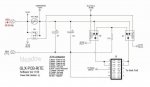
The wiring diagram is to the right. Note that the colors do not match between the Hayward and Pentair wiring blocks.
| Aquarite | Pentair |
| GREEN | BLK/GRD |
| YELLOW | GRN/-DT |
| BLACK | YELLOW/+DT |
| RED | RED/+15 |
- ↑ https://www.troublefreepool.com/threads/aquarite-dead-generic-cells-for-hayward-aquarite.113196/post-1002846
- ↑ https://hayward-pool-assets.com/assets/documents/pools/pdf/literature/salt-chlorination-LITSLTB15.pdf?fromCDN=true
- ↑ https://www.troublefreepool.com/threads/aquarite-dead-generic-cells-for-hayward-aquarite.113196/post-1002993
- ↑ https://www.troublefreepool.com/threads/price-check-on-an-oem-t-cell-15.192861/post-1699587
- ↑ https://www.troublefreepool.com/threads/sanitizing-pains-tried-swg-liquidator-chlorine-tablets-and-bleach-tired-of-fighting-need-help-thinking-ozonator.203644/post-1796773
- ↑ https://www.troublefreepool.com/threads/any-experience-with-chlorinator-pro-replacement-cells.203022/post-1792718
- ↑ https://www.troublefreepool.com/threads/price-check-on-an-oem-t-cell-15.192861/post-1706925
- ↑ https://www.troublefreepool.com/threads/thoughts-on-hayward-aquarite-low-salt-swg.129315/post-1145032
- ↑ https://www.troublefreepool.com/threads/thoughts-on-hayward-aquarite-low-salt-swg.129315/post-1143822
- ↑ https://www.troublefreepool.com/threads/ph-and-acid-base-demand.203597/post-1794221
- ↑ https://www.troublefreepool.com/threads/how-salt-systems-determine-salinity.114565/
- ↑ https://www.troublefreepool.com/threads/aquarite-t15-failing.212388/post-1860565
- ↑ https://www.troublefreepool.com/threads/paper-clamp-on-thermistor-corrected-aqua-rite-generating-problems.132143/post-1168826
- ↑ http://media.digikey.com/PDF/Data%20Sheets/Ametherm%20PDFs/AS322R025.pdf
- ↑ https://www.ametherm.com/
- ↑ https://www.troublefreepool.com/threads/aqua-rite-should-current-limiter-get-very-hot.66309/post-563634
- ↑ https://www.troublefreepool.com/threads/thermistor.193985/post-1709790
- ↑ https://www.troublefreepool.com/threads/aquarite-thermistor.98779/
- ↑ https://www.troublefreepool.com/threads/aquarite-diagnose-troubleshoot-your-own-main-board.167903/post-1489591
- ↑ https://www.troublefreepool.com/threads/hayward-aqua-rite-salt-water-chlorine-generator-thermistor-fix.188323/post-1660300
- ↑ https://www.troublefreepool.com/threads/is-my-thermistor-bad-ohm-reading-question.134144/post-1188497
- ↑ https://www.troublefreepool.com/threads/aquarite-hayward-t-15-new-failure.171969/post-1516645
- ↑ https://www.troublefreepool.com/threads/hayward-aqua-rite-salt-water-chlorine-generator-thermistor-fix.188323/post-1660317
- ↑ https://www.troublefreepool.com/threads/aquarite-diagnose-troubleshoot-your-own-main-board.167903/post-1480706
- ↑ https://www.troublefreepool.com/threads/hayward-aqua-rite-salt-water-chlorine-generator-thermistor-fix.188323/post-1660856
- ↑ https://www.troublefreepool.com/threads/expected-life-of-the-hayward-aquarite-as32-2r025-thermistor.134278/
- ↑ https://www.troublefreepool.com/threads/paper-clamp-on-thermistor-corrected-aqua-rite-generating-problems.132143/post-1168803
- ↑ https://www.troublefreepool.com/threads/aquarite-hayward-t-15-new-failure.171969/post-1516645
- ↑ https://www.troublefreepool.com/threads/expected-life-of-the-hayward-aquarite-as32-2r025-thermistor.134278/post-1189605
- ↑ https://www.troublefreepool.com/threads/paper-clamp-on-thermistor-corrected-aqua-rite-generating-problems.132143/post-1168944
- ↑ https://www.troublefreepool.com/threads/aqua-rite-should-current-limiter-get-very-hot.66309/post-564344
- ↑ https://www.troublefreepool.com/threads/aquarite-hayward-t-15-new-failure.171969/post-1516645
- ↑ https://www.troublefreepool.com/threads/aquarite-swcg-new-t-cell15-0-salt-reading.168828/post-1488509
- ↑ https://www.troublefreepool.com/threads/aqua-rite-display-issue.145855/
- ↑ https://www.troublefreepool.com/threads/aquatrol-not-generating-salt-level-is-at-0.171684/post-1514969
- ↑ https://www.troublefreepool.com/threads/how-to-use-my-own-power-supply-for-aquarite-salt-cell.169333/post-1492337
- ↑ https://www.troublefreepool.com/threads/t-cell-current-sensor-short-relay-k1-stuck-open.190081/post-1674857
- ↑ https://www.troublefreepool.com/threads/t-cell-15-issue.189779/post-1672008
- ↑ https://www.ebay.com/itm/15-24-6106-MOLEX-CONN-HEADER-10-POSITION-4-2mm-VERT-TIN/121416437733?hash=item1c44fbcfe5:g:MKcAAOSwxCxT9hxQ
- ↑ https://www.troublefreepool.com/threads/aquarite-swg-question.211200/post-1851465
- ↑ https://www.digikey.com/product-detail/en/te-connectivity-amp-connectors/5555165-1/A31422-ND/769566
- ↑ https://www.troublefreepool.com/threads/hayward-aquarite-t15-no-lights-after-circuit-board-replacement.209656/post-1840286
- ↑ https://www.troublefreepool.com/threads/aquarite-experts-fw-levels.193340/post-1703936
- ↑ https://www.troublefreepool.com/threads/no-display.189443/post-1688590
- ↑ https://www.troublefreepool.com/threads/aquarite-diagnose-troubleshoot-your-own-main-board.167903/post-1489716
- ↑ https://www.troublefreepool.com/threads/hayward-goldline-aqua-rite-issues-solid-check-salt-inspect-cell.193959/post-1709875
- ↑ https://www.troublefreepool.com/threads/aquarite-diagnose-troubleshoot-your-own-main-board.167903/post-1480879
- ↑ https://www.troublefreepool.com/threads/aquarite-diagnose-troubleshoot-your-own-main-board.167903/post-1488319
- ↑ https://www.troublefreepool.com/threads/lightning-took-out-power-to-aquatrol-display.168439/post-1485894
- ↑ https://www.troublefreepool.com/threads/salt-cell-not-generating.170120/post-1499865
- ↑ https://www.troublefreepool.com/threads/aquatrol-not-generating-salt-level-is-at-0.171684/post-1514277
- ↑ https://www.troublefreepool.com/threads/aquarite-diagnose-troubleshoot-your-own-main-board.167903/post-1489610
- ↑ https://www.troublefreepool.com/threads/no-display.189443/post-1688590
- ↑ https://www.troublefreepool.com/threads/aquarite-diagnose-troubleshoot-your-own-main-board.167903/post-1634705
- ↑ https://www.troublefreepool.com/threads/aquarite-diagnose-troubleshoot-your-own-main-board.167903/post-1634061