Yet another DIY pool controller thread

Katodude

Silver Supporter
Aug 22, 2017
2,592
West Palm Beach/Florida
Pool Size
15000
Surface
Plaster
Chlorine
Salt Water Generator
SWG Type
Hayward Aqua Rite (T-15)
So after reading a bunch of these threads and threatening to do something like this I started to pull the trigger.
Thanks to segalion, jonpcar who have provided very interesting reading, and most of all cmc0619 who ideas I primarily "borrowed"
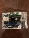
1 Raspberry Pi 3b
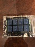
1 Sequentmicrosystems MegaIO relay hat. Plus 1 spare for expansion or when I break this one.

Din rails, plus accessories and a bunch of other stuff I have not ordered yet.

My primary goal for this was to drive 4 valve actuators to go from Pool Mode to Spa Mode. My wife loves the spa and apparently turning 4 valves is too much work (many of you know what I am talking about).

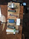
So far I am in the early stages of bench testing this. The Pi is working, the relay hat is working and I can turn the relays off and on via command line and Node Red (thanks again cmc0619).

I will try to document as much of this a possible so that people can copy and improve upon it. However, I got so caught up in the moment tonight I did none of that. Although it is probably a good exercise for me to blow it all away and start over anyway where I can document it.

Things to think about and get comments on about future expansion:

1 Want to measure pH. Seems to be the hardest thing in my pool to keep steady.
2 Set up a Stenner pump to dose acid. (see item 1)
3 Have a single speed pump, should upgrade to a VSP and control that as well (more on this later).
4 Adjust the temperature on my Hayward heater using RS-485 (don't want to cycle the power on and off, just seems kludgy). This item seems the hardest to do, I just cant find the protocol anywhere.
5 Turn my SWG on and off with my pool pump.

Running valve actuators seems pretty simple and is very low risk. If I make a mistake water just goes in the wrong place.

I can do items 3-5 by upgrading my pump to the new Hayward VSP 950 with Omni system for about 2K installed. I can tap one of the relay circuits in the omni to sense spa mode and have my Pi drive the actuators. I figure the pump is worth about $1200 so I am paying about $800 for some automation and the installation which is not a terrible price. BTW for those of you building on top of your Intellicenter configs this would be very similar just with the Hayward version.

Or I can just buy a VSP pump from INYO pools and have my new controller handle everything.

I am happy to answer any questions, and so far this seems like a fairly easy project to do and I am happy to help anyone out.
 

Attachments

  • FC7F6812-C93C-4746-AA32-3DE2395BDB25.jpeg
    FC7F6812-C93C-4746-AA32-3DE2395BDB25.jpeg
    403.8 KB · Views: 133
  • 9A80BF54-D160-454C-869F-27BB89E5747D.jpeg
    9A80BF54-D160-454C-869F-27BB89E5747D.jpeg
    394.5 KB · Views: 132
Hello katodude.
For your description seems you have a one speed pump now, and you plan to buy a VSP. Problem of VSP is the control (integrate the control and monitoring in a DIY open system). Have you think in a cheaper Frequency Variator and a cheap tri-phasic fixed pump? (the two components os a VSP)
 
The Hayward VSPs have two options for control. I can send an 485 signal to it with the %speed I want and it sends a return signal. The problem with that is that it requires the signal be send every second. That just seems like too much can go wrong.

The other option is relay control. With 3 relays you can set 8 different speed settings. This just seems easier to do and with another hat I would have plenty of relays. Also 8 different speed settings is plenty for me.

I am not in a rush to do that, but there are some sales now, and the savings in power might be worth it.
 
The other option is relay control. With 3 relays you can set 8 different speed settings. This just seems easier to do and with another hat I would have plenty of relays. Also 8 different speed settings is plenty for me.
That is definitely the easiest way do do it. I’m not willing to give up complete pump control yet though, haha. One reason I want the total control is that I plan on continuing some experiments with pump rpm/gpm/energy factor once I get all the basics implemented to my satisfaction. At this point it is a bit more like a hobby/obsession rather than a requirement for me.

Kato, welcome aboard the DIY express...your plan is a great one for your situation/requirements. Keep us updated.
 
Ok, I am totally hooked on this build now. All I keep doing is ordering more stuff from Amazon and tinkering.

This Node-Red stuff is really cool and is making this soooo much easier. (I was afraid that I was going to have to learn Python to get this done, which I may still do for kicks).

I just activated Alexa control in the Node-Red and it works!!!

I have ssh enabled on the Pi and I can access Node-Red remotely so I might be able to disconnect the Pi from the monitor and keyboard soon.
 
I have wired up the relays to terminal blocks and tested each relay with an ohm meter to make sure I did not screw up the wiring.

I have all 8 relays wired. I am using one block and the black wires for common. Even number relays wired NO with yellow, odd number relays with red.

For my programming odd number relays will turn the actuators one direction (Spa Mode), and the even will turn the actuators the other way (Pool Mode).

Ordered the 24v AC transformer. And I need to get an actuator (actually 4 of them, but I should test one first).

Anybody have any suggestions on valve actuators or are they pretty much all the same?

D00C08EB-27E6-427D-B44D-D291339DEAD2.jpeg
 
You did it! NICE!

4 Adjust the temperature on my Hayward heater using RS-485 (don't want to cycle the power on and off, just seems kludgy). This item seems the hardest to do, I just cant find the protocol anywhere.

I commented on the @jonpcar thread about your heater because i hadn't seen this but I'll add it here for continuity:
"I just looked up the manual on your Hayward H400FDP. It operates the same as my RayPak 406A. The Hayward outputs a 24VAC signal and you can use a dry relay to switch between pool, SPA or Off. Because there are three states, you'll need two relays. One to enable the heater mode, and one to select between Heat/Pool temp. The temperature has to be hardset out of band and can't be controlled via remote. " You'll want to feed the hot side, which is a misnomer because it's AC, thru the "Heater Enable" (what I call it) relay and then switch that relay on, which outputs that signal to the 2nd relay which switches Heat or Pool wire selection to complete the circuit.

Anybody have any suggestions on valve actuators or are they pretty much all the same?

I think they're all pretty much the same. When I do it I'm just going with the Intermatic because they're the cheapest on Amazon and they have decent reviews (80% 4/5 star reviews).
 
Hello Katodude. I see you are using the megaio board.

I have put my eyes on this great board because it is really ingenious and amazing full of great things as the most perfect complement of a raspberry pi (8 full relays,8 12bit ACD, 1 12 bit DAC, optos, stackable...).

I have been revised the python code and seems realative easy to implement a full set of components to integrate in Home Assistant.

So you've convinced me to include this as a basic for my project instead of the actual direct gpio relays. I have to buy one card, and create proper components, so meanwhile is only a TODO thing.

Thanks for your recomendation.
 
  • Like
Reactions: cmc0619
Don’t thank me, thank cmc, it was his idea, I am just good at copying.

But let me tell you I love this board. It is sooo easy to use. I am happy that I bought two since I am now going to stack them and expand my project.

I am also going to use one of the ADC ports to connect to my flow switch so I can double check that I have flow before turning things on like the chlorinator and heater. I just need to measure what my chlorinator routes as a voltage through the switch and measure for that.
 
I commented on the @jonpcar thread about your heater because i hadn't seen this but I'll add it here for continuity:
"I just looked up the manual on your Hayward H400FDP. It operates the same as my RayPak 406A. The Hayward outputs a 24VAC signal and you can use a dry relay to switch between pool, SPA or Off. Because there are three states, you'll need two relays. One to enable the heater mode, and one to select between Heat/Pool temp. The temperature has to be hardset out of band and can't be controlled via remote. " You'll want to feed the hot side, which is a misnomer because it's AC, thru the "Heater Enable" (what I call it) relay and then switch that relay on, which outputs that signal to the 2nd relay which switches Heat or Pool wire selection to complete the circuit.

It seems that way, I have been reading the manual for the heater as well.
The other option is they discuss a remote thermostat “2 wire” option. I am guess that is just a cycle on and off of the heater? Do I just close the circuit on that or do I apply 24VAC? Since I decided I am going to plumb in a thermocouple like Jon did, I can have the automation cycle the heater off and on. I just don’t want to cycle the power relay, I am hoping this 2 wire solution is like an on/off switch.
 

Enjoying this content?

Support TFP with a donation.

Give Support
It seems that way, I have been reading the manual for the heater as well.
The other option is they discuss a remote thermostat “2 wire” option. I am guess that is just a cycle on and off of the heater? Do I just close the circuit on that or do I apply 24VAC? Since I decided I am going to plumb in a thermocouple like Jon did, I can have the automation cycle the heater off and on. I just don’t want to cycle the power relay, I am hoping this 2 wire solution is like an on/off switch.

Your sig says you have an attached spa. You're probably better off going with the 3 wire option. They both work the same way. You can create two presets on your heater, one for pool temp and one for spa temp. The 3 wire chooses between the two temps. The 2 wire chooses between 1 temp so, yes, it's essentially an on/off switch for the call for heat (CFH) function.

Since you're using a thermocoupler, you'd want to set the highest temp you'd ever want your pool/spa to be and then manage the temp from the controllers thermocoupler input and some programming logic you define.

You don't want to apply 24VAC *to* the heater from the controller. EVER. The heater provides the 24vac, you're just dry switching it back to either the pool/spa wire. I don't even have a power relay on my heaters 230v input. It goes direct to the circuit breaker and is on 24/7 and I use the CFH relays to control when it fires up.
 
Ok, I have made a little progress. Got a 24VAC transformer (the wrong one since I will need one that will work with 240 on the pad, but for bench testing it will be fine).

The project like all projects are being affected by scope creep. Now I just want to control everything with this. Bought some high voltage relays from ASI and will install another megaio hat to control those. All input power will be 240 since every big device runs on 240. I have a transformer for 24VAC to drive the actuators, and to trip the high voltage relays. A 10amp 5v power supply to drive the Raspberry Pi and MegoIO relay boards.

I have wired up all the relays for the actuators and tested the voltages and they are all good. The test actuator that I have does not seem to be behaving properly, even when I run it directly to the transformer. Going to take it apart later to see what is going on, I might just have a defective unit.

The Node-Red code is working really well. Although I am going to want to clean that up later since I have hard coded a lot of stuff that should be more variable based.

I am getting close now.
 

Attachments

  • 1035A2BD-0AD9-4FB4-B633-F9A3F4473DBA.jpeg
    1035A2BD-0AD9-4FB4-B633-F9A3F4473DBA.jpeg
    499.8 KB · Views: 103
  • Like
Reactions: cmc0619
Ok, I have made a little progress. Got a 24VAC transformer (the wrong one since I will need one that will work with 240 on the pad, but for bench testing it will be fine).

Keep in mind 240v residential power in the US is just two opposed phases of 120v. So you can hook the 120v transformer to a hot leg (doesn't matter which of the two), and then connect the other wire to common (the white one, usually) and ta-dow you have 120v power. This is the exact way your house is wired.
 
  • Like
Reactions: DavidArmenB
Well that makes a lot of sense. Hmm, now I am going to have to check if the chlorinator and the heaters are wired to 240 or 120? It’s only going to be a minor change to wiring.

It’s time to start wiring up the second hat to control those ASI relays (which look really nice btw). 1 for the chlorinator, 1 for the heater (I want to shut power to the heater when I am not using it), and 1 for the acid injecting stenner pump.

I also decided I am not going to change my pump for right now, so I need to order another higher powered relay probably something around 30amps that also have a 24VAC coil.

The Intermatic valve actuator I ordered was defective (I think on of the microswitches is broken), so that has to go back. I ordered a Pentair Intellivalve to try that sucker out and see if I like it.
 
  • Like
Reactions: cmc0619
The Intermatic valve actuator I ordered was defective (I think on of the microswitches is broken), so that has to go back. I ordered a Pentair Intellivalve to try that sucker out and see if I like it.

I'll be interested to see what you thing vs the two models. That's the only thing left to do on my project and is the single most expensive part so I've been dragging my feet on deciding which to get..
 
One more thing I'd point out. You want your relays to switch the hot side. It looks like you have them joining the - side to the + side in the relay. That can cause arcing and will generally reduce the life of your relays. The relay should be wired so they are in the middle of the + wire and the - side should go to the other terminal of your load. (load in your case being the larger relays that switch mains power and your actuators). This also applies to mains power relays as well.
 
Great piece of information, which causes another questions. The only power going to the MegaIO relays is from the 24VAC transformer. How do I determine which is the hot side. Both wires are yellow with a block cover.

The yellow and red wires coming out of the relays are both coming out of the normal closed pole. I am just using yellow and red to distinguish odd from even number relays. Using even to go one direction on the actuator and odd for the other.

I was kind of disappointed in the Intermatic. It just seemed to behave oddly. Might just have been defective, in any case it is going back. The Pentair is on its way.
 
Great piece of information, which causes another questions. The only power going to the MegaIO relays is from the 24VAC transformer. How do I determine which is the hot side. Both wires are yellow with a block cover.

Good question. I don't think it matters. In home wiring, you want to switch the hot for safety reasons. In our implementation it probably doesn't matter much since it's only 24v. I'd just make sure that one side of your transformer goes to the A1 (or A2) on your big relays, and the other side of the transformer, that you switch, ends up on A2 (or A1). The bigger point is you don't want your mega IO relays joining the two sides, you want that connection made at the load.
 
Correct, just to confirm. One side of the 24VAC transformer goes to A1. The MegoIO provides power to A2 from the NC section of the relay from the other side of the 24VAC transformer. That will cause the relay to fire.

That will turn on the ASI relays, that I will wire with the hot end of the 120v circuit for the chlorinator, heater, and Stenner pump. I will wire the neutral directly to the devices. I will wire two more dry relays to turn the heater on and off and select pool or Spa mode.

Now I just need to buy a bigger relay for the pool pump since it is 240V and a whole lot of amps. Any suggestions?

That looks right to me! Check out your stenner pump too. I have an Econ-T that actually operates on 24VDC. Not sure which model you have but if it has a big brick as a plug, that's a power converter, and it's probably using some other kind of voltage to actually run the pump. I unscrewed the end of mine (conveniently threaded) and plugged it directly into a meanwell 24v DC power supply. I talk about it in my youtube.

I saw you were looking at the 950 Omni so I looked up the manual. At 230V that pump draws 11amps max, so if you account for the 80% rule you only need a relay that can handle 13.75 amp inductive loads. You could use the same socket, relay and MOVs I'm using on my 1.5HP WhisperFlo which are good to 15amps.

Also, since you're using the ASI relays. If you have a lot of them and want to reduce your wiring, check out their busbars. If you sit your relays next to each other on the DIN rail, you only have to run one wire to the whole set and the busbar distributes the current to the rest of them. Good for things like the A1 of your 24Vac and also the mains voltage if you're on the same phase for multiple relays.
 

Enjoying this content?

Support TFP with a donation.

Give Support
Thread Status
Hello , This thread has been inactive for over 60 days. New postings here are unlikely to be seen or responded to by other members. For better visibility, consider Starting A New Thread.